|
<< Click to Display Table of Contents >> Vertical PLC mirror with standard graphics |
  
|
|
<< Click to Display Table of Contents >> Vertical PLC mirror with standard graphics |
  
|
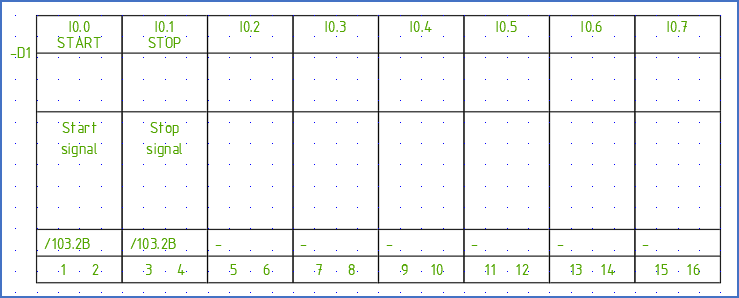
Figure 1104: This is an example of a vertical PLC mirror (8 channel digital input with 2 connection points for each input)
Creating a vertical PLC mirror with standard graphics is a process similar to how a horizontal mirror is created, as described in the previous sub-topic.
This description covers an effective way of creating a complete vertical PLC mirror. To make it more exciting (?!), it will contain a combination of two kinds of I/O's.
Let us therefore assume that we need a PLC mirror with 4 digital outputs with 1 connection point each, and 4 digital inputs, also with 1 connection point each.
Contrary to the case with a horizontal PLC mirror, no "table header" is included in a typical vertical PLC mirror. Therefore, the step that was part of the process for the horizontal PLC mirror with inserting and editing a standard PLC mirror, is excluded.
Therefore, start with the 1. New... command.
In the Symbol data dialogue, specify Symbol name, Description, Symbol type, and Resource Category, as shown in the figure below.
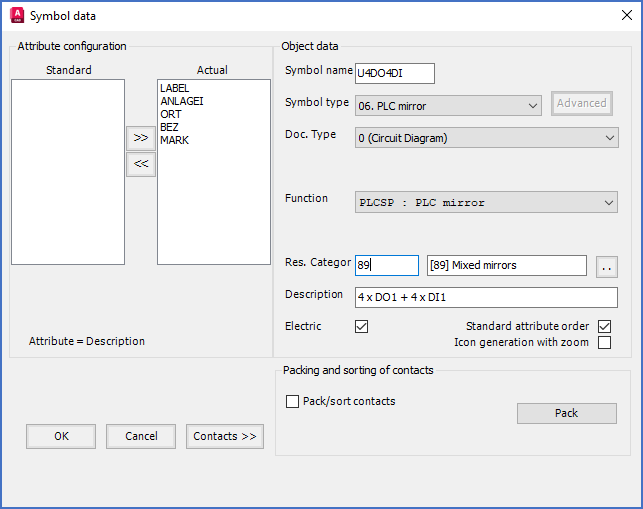
Figure 1104: In the "Symbol data" dialogue, you specify "Symbol name", "Description", and "Resource Category".
Click the Contacts >> button to define the first I/O.
Deselect No graphics, select Vertical orientation, check Attribute, select #DO1 function code, and specify appropriate default connection point numbers according to the product that you intend to use.

Figure 1104: In the "Contact" dialogue, you specify function code (type of I/O) and connection point numbers for each I/O.
Click OK and insert the I/O with the associated function object as shown in the figure below. The red cross symbolises the insertion point of the function object.
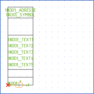
Figure 1105: The first I/O has been inserted.
Continue with the three other digital outputs in the same way. Then change to function code to #DI1 and continue with the four remaining inputs.
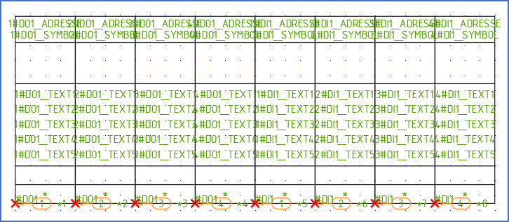
Figure 1106: All I/O's with their respective function objects have been inserted. Please note where the insertion points of them have been placed, marked with red crosses in the figure.
Click Cancel in the Contact dialogue to return to the Symbol data dialogue.
In the Symbol data dialogue, make any needed final adjustments, and then click OK to specify the insertion point of the PLC mirror. Place the insertion point in the upper left corner of the symbol.
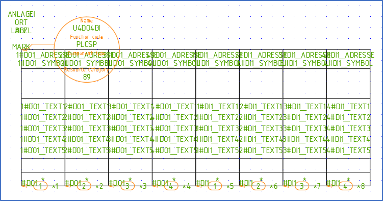
Figure 1107: The insertion point has been defined. Therefore, the symbol object as well as the item designation attributes, are in place.
Obviously, the symbol object need a little rotating to be readable, and the attributes must be adjusted both regarding text justification and position. The ROTATE command takes care of the symbol object, and the Attribute adjustment tool of the attributes.
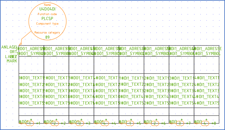
Figure 1108: The symbol object has been rotated, and the attributes adjusted.
As were the case with the horizontal PLC mirror, it can be a good idea to give a hint about what kind of I/O's the mirror contains. Confusing inputs with outputs, or the other way around, can otherwise become an unnecessarily common mistake. You could for example solve this by adding a text to each I/O, like in the figure below.
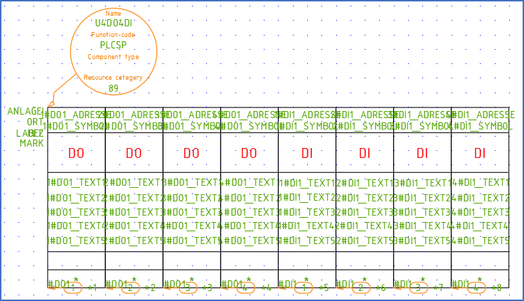
Figure 1109: Texts have been added to clarify the type of each I/O. You could argue that the number of connection points also could have been included in the text, but you can see that from the number of connection point numbers anyway.
Next, the function objects can be rotated to offer better visibility, even if that is not necessary at all. Please note that you can rotate them all with one single ROTATE command.
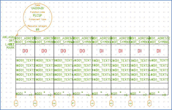
Figure 1110: The function objects have been rotated, which makes it easier to see the details of the symbol.
Finally, the cross-references should be adjusted so that they are displayed consistently with the other attributes. This means that they should be centred and moved upwards, and to the right, so that they are placed in the middle of the now empty second box, counted from the bottom. The Attribute adjustment tool is perfect for this task, which can be done in sequence, without exiting the feature. The cross-references are displayed with their respective function codes, in this case #DO1 and #DI1.
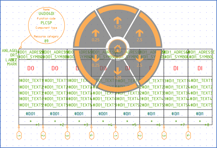
Figure 1111: The cross-references have been adjusted with correct text justification and position using the "Attribute adjustment tool", whic is visible in this figure.
Before saving the symbol, it is a good idea to consider the I/O numbers. Please adjust the default of the I/O numbers to be consistent with the product that the PLC mirror is intended to be used for. The I/O numbers (the physical addresses) are represented by attributes with names ending with _ADRESSE. Edit them using double-click, DDATTE/EDIT or any other proper tool.
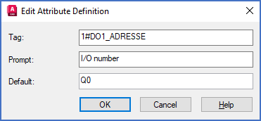
Figure 1111: The default for the I/O number of the first I/O in the PLC mirror is edited with the DDATTE/EDIT command.
In this example we assume that the four digital outputs have I/O numbers Q0 - Q3, and that the eight digital inputs have I/O numbers J0 - J3.
You can then save the symbol using the 2. Save command, insert it, and test it.
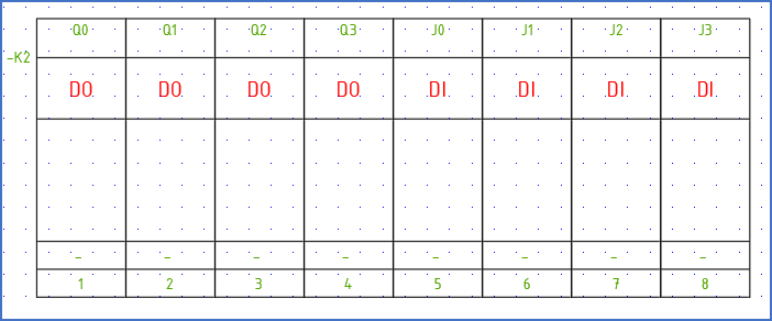
Figure 1112: The PLC mirror is ready, inserted, and ready to be used.
Hopefully, the new PLC mirror will leave nothing else to be desired.