|
<< Click to Display Table of Contents >> Horizontal PLC mirror with standard appearance |
  
|
|
<< Click to Display Table of Contents >> Horizontal PLC mirror with standard appearance |
  
|
This description covers a very effective way of creating a complete PLC mirror similar in appearance with the standard PLC mirrors of the IEC1082 symbol library, but with a combination of I/O's that is not available in any standard PLC mirror.
Let us assume that we need a PLC mirror with 4 digital outputs with 2 connection points each, and 8 digital inputs, also with 2 connection points each.
Start by inserting a standard PLC mirror.
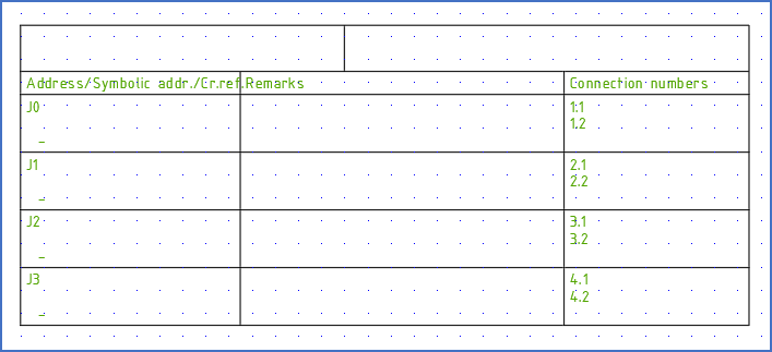
Figure 1042: Any standard PLC mirror will do. In this case, we selected a 4 channel digital input.
Select the 3. Edit command, and select the newly inserted standard PLC mirror, which will then be opened for editing.
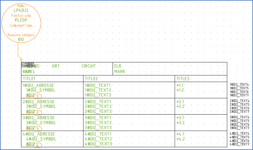
Figure 1043: The standard PLC mirror has been opened for editing.
Adjust the Symbol name, the Description and possibly the Resource Category by double-clicking the symbol object and making the adjustments in the Symbol data dialogue.
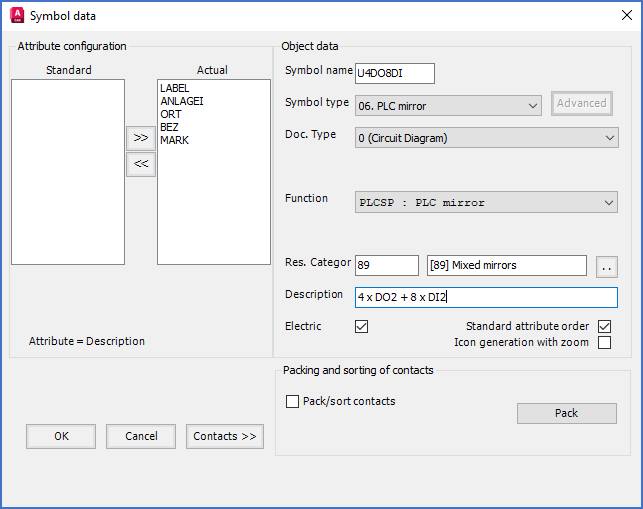
Figure 1044: In the "Symbol data" dialogue, you adjust "Symbol name", "Description", and "Resource Category".
Since there is no standard resource category for PLC mirrors with mixed types of I/O's available, you could select one of the categories that do exist, or add a new one, perhaps 89 for mixed mirrors, or something else that you prefer. Adding resource categories is made in the Catalogue according to the description found here.
Click OK in the Symbol data dialogue, and then delete all existing I/O's in the PLC mirror, leaving only the table header and the Symbol object, like shown in the figure below.

Figure 1045: The Symbol object shows the new symbol name. All I/O's of the standard mirror that we started from have been deleted.
A hint for anyone viewing the new mirror about its content might be a good idea. A simple text in the upper right corner could serve that purpose, like shown in the figure below.

Figure 1046: A text in the upper right corner is used to indicate what kind of a PLC mirror this really is.
Next, the function objects, or in other words the I/O's, should be defined. Therefore, yet again double-click the symbol object. Then click the Contacts >> button to define the first I/O.
Deselect No graphics, select Horizontal orientation, check Attribute, select #DO2 function code, and specify appropriate default connection point numbers according to the product that you intend to use.
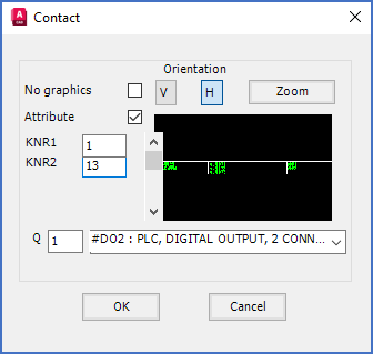
Figure 1047: In the "Contact" dialogue, you specify function code (type of I/O) and connection point numbers for each I/O.
Click OK and insert the I/O and associated function object as shown in the figure below. The red cross symbolises the insertion point of the function object.
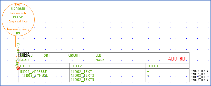
Figure 1048: The first new I/O has been inserted. The red cross in this figure does not turn up in reality. It has been added to this figure to show where the insertion point of the function object (the I/O) should be placed.
Continue with the three other digital outputs in the same way, as shown in the figure below.
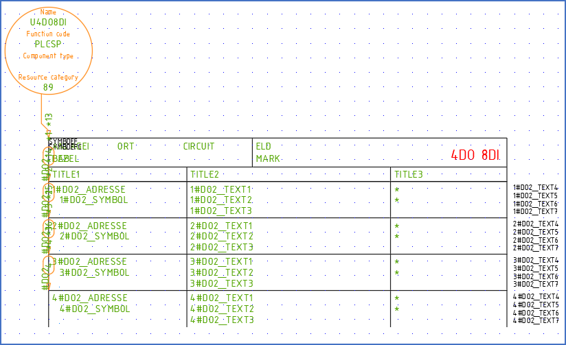
Figure 1049: All digital outputs have been defined and inserted.
Then continue with the digital inputs in the same way.

Figure 1050: Function code "#DI2" means digital input with two connection points.
Work your way through all the I/O's of the mirror. If you happen to misplace one of the I/O's, do not panic! Simply continue with the remaining ones. You will get the opportunity to make any necessary corrections later on.

Figure 1051: All I/O's have been defined and inserted. The lower end of the symbol needs some attention though.
When all I/O's have been defined and inserted, click the Cancel button in the Contact dialogue. You then return to the Symbol data dialogue. There, click the OK button to exit that dialogue as well.
Now is a good time to adjust the positions of any misplaced I/O's or similar.
Then add a horizontal line in the lower end of the mirror, as shown in the figure below.

Figure 1052: A horizontal line in the bottom of the PLC mirror makes it graphically complete.
Use the ROTATE command to rotate all function objects in a more readable way. Please note that you can select and rotate them all at once.
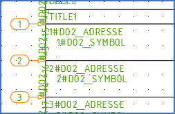
Figure 1053: The function objects have been rotated with the "ROTATE" command, for better visability.
Use for example the Attribute adjustment tool to rotate all 12 cross-reference attributes to be horizontal, as all other attributes are. The cross-reference attributes are displayed with the respective function code, as shown in the figure below (in this case #DO2 and #DI2). Please note that you can select and rotate them all cross-references at once.
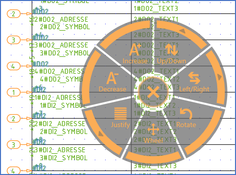
Figure 1054: The cross-references have been rotated using the "Attribute adjustment tool".
Then continue to move them, so that they are placed consistent with the other attributes. You can use the same tool for that. You do not even have to exit it.
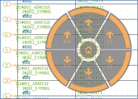
Figure 1055: Without exiting the "Attribute adjustment tool", the same attributes have also been moved downwards and to the right, so that they are consistent with the others attributes of the mirror.
In the figure below, the symbol is shown with all attributes in their final positions.
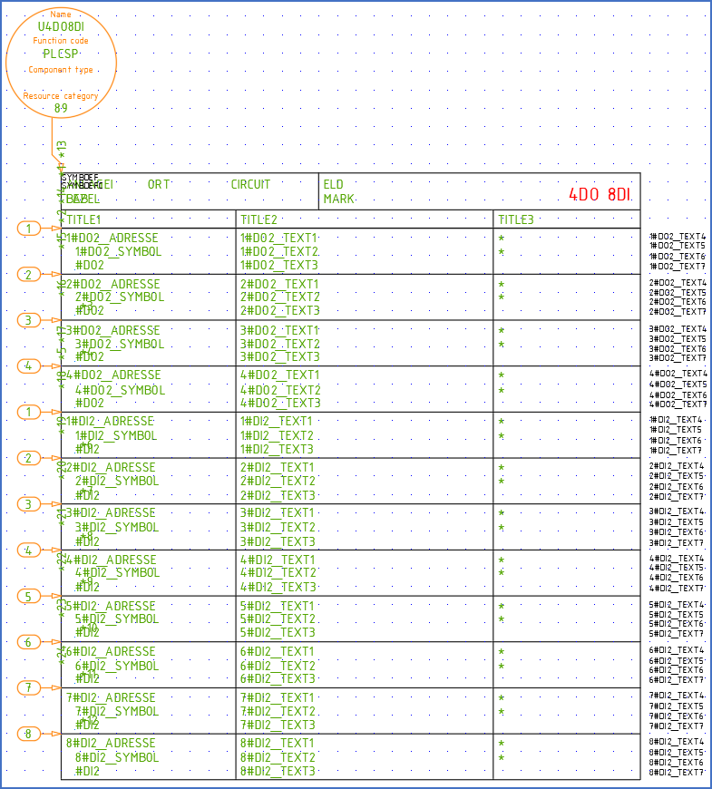
Figure 1056: All attributes are now in their final positions. Do not be fooled about the positions of the connection points. Their true positions are defined by the asterisks to the right, while the default values are seen in somewhat odd positions that do not matter.
Before saving the symbol, it is a good idea to give the I/O numbers some consideration. A PLC mirror like the one in this example is probably intended for a specific product. Therefore, please adjust the default of the I/O numbers to be consistent with that product. The I/O numbers (the physical addresses) are represented by attributes with names ending with _ADRESSE. Edit them using double-click, DDATTE/EDIT or any other proper tool.
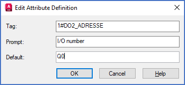
Figure 1057: The default for the I/O number of the first I/O in the PLC mirror is edited with the DDATTE/EDIT command.
In this example we assume that the four digital outputs have I/O numbers Q0 - Q3, and that the eight digital inputs have I/O numbers J0 - J7.
After that, it is time to save the symbol. Therefore select the 2. Save command, and select the entire content of the new symbol including the function objects and the symbol object. When you confirm the object selection, the symbol is saved and thereby removed from the drawing sheet that you are working in.
Insert the PLC mirror and test it!
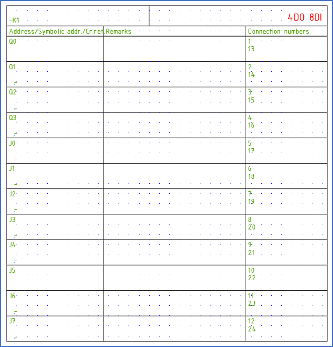
Figure 1058: The PLC mirror is ready to use.
Hopefully, the result fulfils all your dreams, which have then finally come true!