|
<< Click to Display Table of Contents >> Terminal macros |
  
|
|
<< Click to Display Table of Contents >> Terminal macros |
  
|
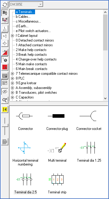
The commands used to draw terminals - terminal macros - are found in the first resource category in the Symbol Insert Tool:
a – Terminals.

Figure 1551: Terminal macros are found in resource category "a".
No less than four commands are available for terminals:
Command |
Description |
|---|---|
Terminal symbols with 1.25 mm diameter comply with IEC617 and constitutes the recommended choice.
|
|
Enlarged symbols with 2.5 mm diameter circles are a violation of IEC617. They are therefore not recommended.
|
|
Terminal strip symbols are intended for so-called connection diagrams and do not belong in circuit diagrams.
|
|
The Multi terminal macro is a legacy feature supporting terminals with user defined appearances. Please note, that many graphical variants are supported by the two standard terminal macros. The need for making user defined terminal symbols is therefore very limited.
|
With these macros, you can draw an entire terminal list with one single command, but also insert single terminals if you like.
In almost all cases, it is more effective to draw the lines first, and insert terminals upon the lines, instead of the other way around. If you start with the lines, the terminals are automatically placed on the lines that you specify. The lines are automatically broken creating a gap of the correct size for the symbol that you have chosen.
Please refer to the sub-topics that are listed below for a detailed description of how to use the terminal macros.
•Detailed terminal symbol dialogue
•Simplified terminal symbol dialogue
•Terminal numbering when inserting terminals