|
<< Click to Display Table of Contents >> Filter conditions |
  
|
|
<< Click to Display Table of Contents >> Filter conditions |
  
|
Filter conditions are used to compare values fetched from specified fields in the Drawing Manager with fixed text values using a set of operators.
Filter conditions have the following basic components:
[Value from a Drawing Manager field] IS [Operator] [Value to compare with]
All fields in the Drawing Manager as specified in the currently used mask can be used for filtering.
The operator can be either of the ones that are listed in the table below.
Operator |
Symbolic representation |
Explanation |
|---|---|---|
EQUAL TO |
= X |
Must be exactly equal to the value to compare with |
NOT EQUAL TO |
<> X |
Must not be equal to the value to compare with |
STARTING WITH |
= X* |
Must start with the value to compare with |
NOT STARTING WITH |
<> X* |
Must not start with the value to compare with |
ENDING WITH |
= *X |
Must end with the value to compare with |
NOT ENDING WITH |
<> *X |
Must not end with the value to compare with |
CONTAINING |
= *X* |
Must be contained within the value to compare with |
NOT CONTAINING |
<> *X* |
Must not be contained within the value to compare with |
The value to compare with can be any combination of characters.
Example:
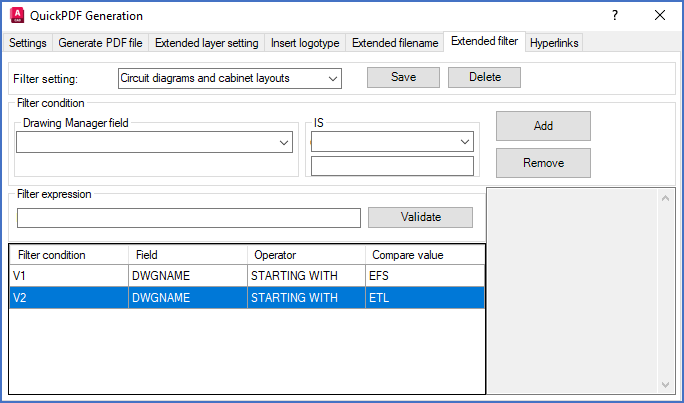
DWGNAME IS STARTING WITH EFS
DWGNAME is the field in the Drawing Manager that contains the filename.
In a project like for example the Demo IEC1355 English, circuit diagram drawing sheets have filenames starting with EFS, while for example cabinet layout drawing sheets will not. A condition like the one above can therefore be used to exclude other drawing sheets than circuit diagrams.
Each filter condition is automatically associated with a variable that in turn is used in a filter expression, which defines the relationship between the conditions, if you have more than one. If you only have one filter condition, the filter expression must refer to that (V1).
The variables are simply called V1, V2, V3 and so on.

Figure 1405: Two filter conditions are visible here.
In the sub-topics that are listed below, you will find detailed descriptions of the table of conditions in the bottom of the dialogue box, the interpretation of the conditions in that table including the relationship between them, and how you can create and remove conditions in the table.
Filter expressions are explained in a separate sub-topic with that very name.