|
<< Click to Display Table of Contents >> Detailed example of a vertical contact mirror |
  
|
|
<< Click to Display Table of Contents >> Detailed example of a vertical contact mirror |
  
|
The description below assumes that you want to create a vertical contact mirror.
Select the 1. New... command.
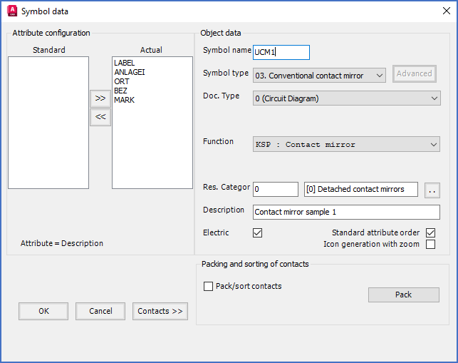
Figure 875: Specification for a typical conventional contact mirror
In the Symbol data dialogue box, specify Symbol name, Symbol type, Document type, Resource category, and Description, as shown in the figure above.
Please note that the Function code for a conventional contact mirror is always KSP. No other option is available.
The next step is to define the contacts. You do that from the first contact on top, and then one by one, downwards. Please note how you should place the insertion points. That is illustrated in the figures below.
Click the Contacts >> button, to define the first contact, which is the first make main contact.
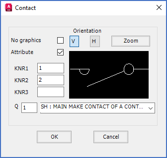
Figure 876: The "Contact" dialogue box
Select Vertical Orientation, Attribute (to get a dynamic contact mirror), connection point numbers 1 and 2, and SH (main make contact).
Click OK and place the contact according to the figure below.
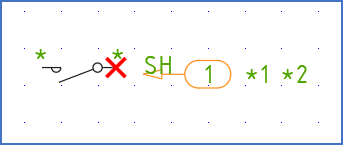
Figure 877: The red cross shows where the insertion point is placed.
Continue with the following two main make contacts in the same way.
Then add the break help contact.
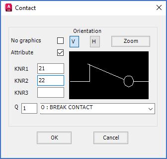
Figure 878: A break help contact has "o" as function code.
Then comes the first make help contact.
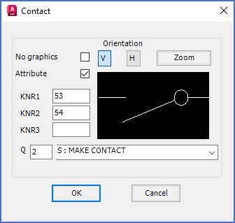
Figure 879: A make help contact has "S" as function code.
Continue with the last contact in the same way.
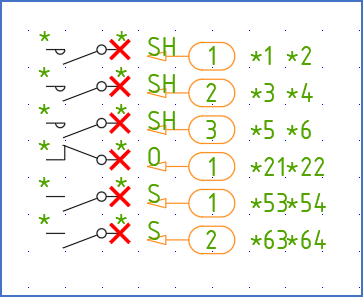
Figure 880: All contacts according to the plan have been inserted. The red crosses shows where the insertion points for the contacts are.
When all contacts are in place, click Cancel to return to the Symbol data dialogue.
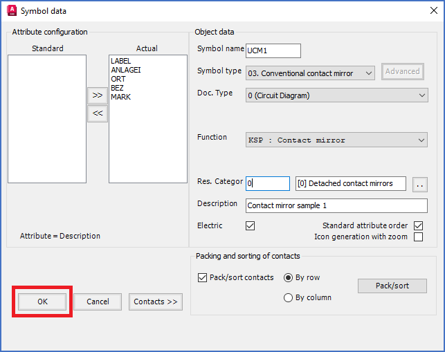
Figure 881: When you click the OK button in the Symbol data dialogue, you are asked to specify the insertion point of the symbol.
Click the OK button. You are then asked to specify the insertion point. Place that 5 mm (2 snap steps) above the uppermost contact.
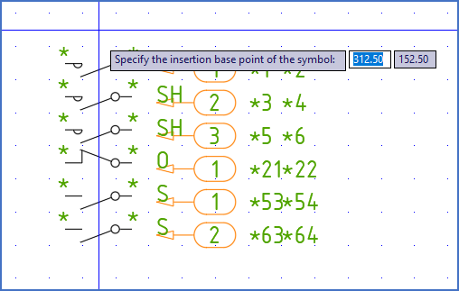
Figure 882: Place the insertion point like this, 5 mm above the uppermost contact.
Place the insertion point as shown in the figure above. When that is done, you will get a result like shown in the figure below. As you can see, there is room for improvement.
The attributes must be moved down below the symbol. You can do that using the MOVE command, or perhaps with the Attribute adjustment tool (the wheel menu).
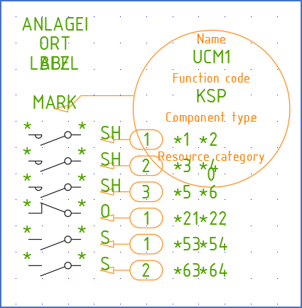
Figure 883: The result is somewhat messy. The attributes must be moved, and rotating the symbol object seems like a good idea.
A few clicks later, the messy appearance in the figure above, has been replaced with the sober order shown in the figure below.
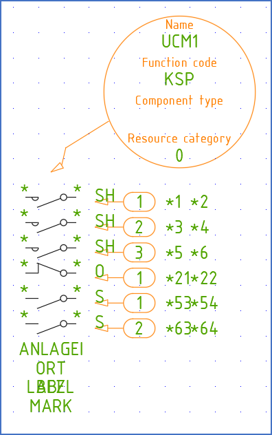
Figure 884: The attributes have been moved below the symbol and the symbol object has been rotated so that is does not interfere with the graphics.
Finally, a mechanical link should connect the contacts. You create that by drawing a line in the MECHANIK layer. To end the line in both ends as precise as in the figure below, it is a good idea to set the SNAP to 0.25 mm before drawing the line. Please do not forget to restore the original 2.5 mm SNAP afterwards.
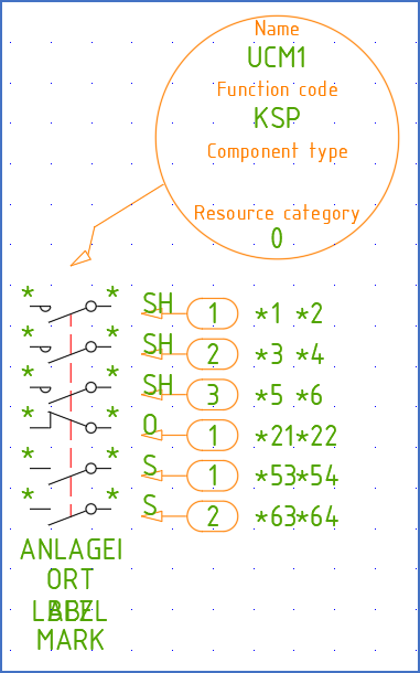
Figure 885: A mechanical link has been added.
Then select the 2. Save command to save the contact mirror. As always, please make sure to include everything that should belong to the symbol, including the Symbol generator objects. Likewise, make sure not to include anything that should not belong to the symbol.
The contact mirror is then ready to use.
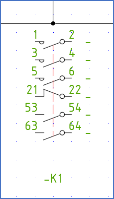
Figure 886: The finshed symbol has been inserted and now works fine.
The figure above shows the finished contact mirror inserted as it should, with the insertion point in the crossing between the two lines.