|
<< Click to Display Table of Contents >> Appearance section |
  
|
|
<< Click to Display Table of Contents >> Appearance section |
  
|

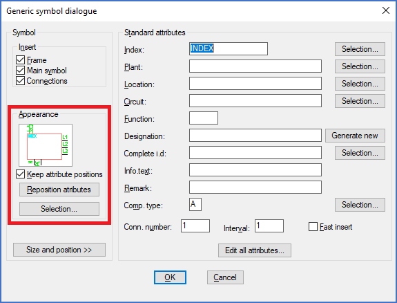
Figure 923: The "Appearance" section of the "Generic symbol dialogue"
In the Appearance section to the left in the dialogue box, you can select the main appearance of the Generic symbol by clicking the Selection… button, which displays a second dialogue box, as shown in the figure below.

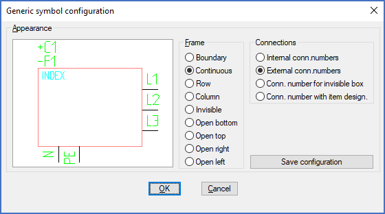
Figure 924: This dialogue box is used to select the appearance of a "Generic symbol".
•To the left you select how the box should look. To the right you define the look of the connections.
•Two combinations are especially useful to comply with current IEC standards:
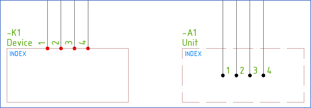
a.A Continuous box combined with External conn. numbers results in a Generic symbol that should be interpreted as a device that is connected “on the outside”.
b.The Boundary option for the box, where the box is drawn with a dash-dot line, in combination with Internal conn. numbers, also complies with the current IEC standard, but it has a slightly different interpretation. In this case, the Generic symbol symbolises a larger unit containing several parts, where the connection is made inside the unit. It may for instance be a whole cabinet.

Figure 925: A "device" to the left and a "unit" to the right, are here shown with a DESIGN layer setting.

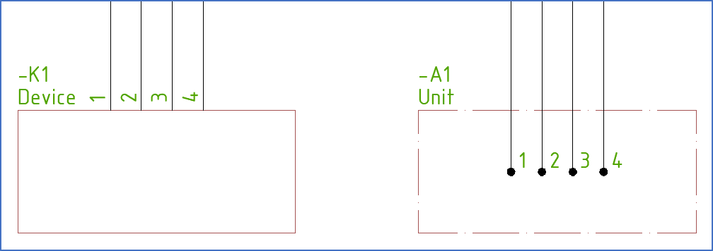
Figure 926: The same generic symbols are here shown with a PLOT layer setting.