|
<< Click to Display Table of Contents >> Symbol type |
  
|
|
<< Click to Display Table of Contents >> Symbol type |
  
|
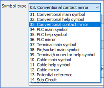
The choice of Symbol type determines a number of important factors for the rest of the procedure of creating a new symbol.

Figure 812: Symbol type selection
As has already been described briefly, the symbols in cadett ELSA mainly lives in four different and from each other separated “continents”, each with its own type of item designations. The item designations of these four “continents” are composed separately. Therefore, they can vary a lot from each other. Within each “continent”, you can typically have main symbols, help symbols, and mirror symbols. On a fifth "continent", you will find potential references, with their unique kind of "item designations", which is the "potential" or "signal name". Besides from all these symbol types, you can also create sub-circuits, which are combinations of other symbols and objects, like lines, giving a total of 14 symbol types to choose from.
Please refer to the table below.
Symbol type |
Item designation type ("continent") |
Comment |
|---|---|---|
01. Conventional main symbol |
Conventional |
Main symbols for devices that are not PLC's, terminals, or cables, are called conventional main symbols. A main symbol defines a physical device. An index specifies which resource (article) to use.
|
02. Conventional help symbol |
Conventional help symbols are connected to conventional main symbols. Help contacts are typical conventional help symbols.
|
|
03. Conventional contact mirror |
A conventional contact mirror is used to mirror help symbols like contacts. The contact mirror defines which contacts that are available, both used ones, and unused.
|
|
04. PLC main symbol |
PLC |
The PLC main symbol has an index specifying the device. Common connections like power feeding are often placed in the main symbol.
|
05. PLC help symbol |
The PLC help symbol is also called an I/O symbol. It shows one single input or output for a PLC, with the connection points for that I/O.
|
|
06. PLC mirror |
A PLC mirror mirrors multiple inputs or outputs for a PLC, typically for a single card.
|
|
07. Terminal main symbol |
Terminals and connectors |
Standard terminal symbols belong to this type.
|
08. Pin/socket main symbol |
Standard pin and socket symbols belong to this type.
|
|
09. Terminal/connector help symbol |
A terminal or connector help symbol, is a help symbol referring to a terminal or pin/socket main symbol. It must have both terminal group name and terminal number to correctly connect to a specific terminal.
|
|
10. Cable main symbol |
Cables |
It is possible to create a user defined cable main symbol and to configure the standard cable macro to use that instead of the corresponding standard symbol. The cable main symbol contains the index and electrical data of the cable.
|
11. Cable help symbol |
The cable help symbol is also called a cable core symbol. Each cable core is defined by one single cable help symbol.
|
|
12. Cable mirror |
A cable mirror defines and mirrors all cable cores of a cable.
|
|
13. Potential reference |
Potentials |
User defined potential reference symbols are seldom needed, but they are supported.
|
14. Sub-circuit |
N/A |
A sub-circuit is a copy of a sub-set of a drawing sheet, typically containing multiple symbols, lines, and connection points. It can be used for cabinet layouts or other types of drawing sheets as well.
|
More information about these symbol types, including advice about creating and maintaining symbols of each type, is found in a topic named Specific details for different symbol types.