|
<< Click to Display Table of Contents >> Insert function object for I/O |
  
|
|
<< Click to Display Table of Contents >> Insert function object for I/O |
|

Figure 850: The "OK" button
After clicking the OK button, as shown in the figure above, you are asked to insert the function object in a suitable position. When you have done that, you return to the Contact dialogue box, where you can define the next I/O.
If you have already defined all the I/O's you want to have, you should use the Cancel button.
Positioning the function object correctly is in fact not trivial. Therefore, a detailed description of how the insertion points are placed is provided below.
In principle, there are four separate cases:
•Vertical with graphics
•Vertical without graphics
•Horizontal with graphics
•Horizontal without graphics
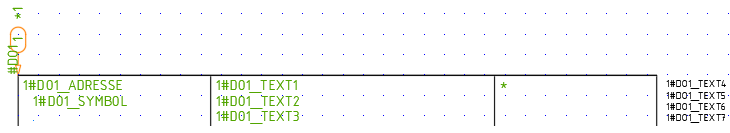
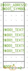
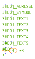
It has been said that a picture is worth a thousand words, so instead of spreading the text about how the insertion points of the function objects are placed, we illustrate this with the graphic table below. The insertion points are placed in the arrowheads.
Horizontal |
Vertical |
|
|---|---|---|
With graphics |
|
|
Without graphics |
N/A |
|