|
<< Click to Display Table of Contents >> Values section in Wire-number dialogue |
  
|
|
<< Click to Display Table of Contents >> Values section in Wire-number dialogue |
  
|
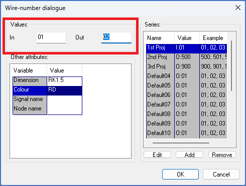
The Values section of the Wire-number dialogue is marked with a red box in the figure below.

Figure 1448: The "Values" section of the "Wire-number dialogue"
In this section, you have two fields:
•In
•Out
These two fields are described below.
•In the In field, you specify the wire-number of the incoming wire, if there is one. If there is no incoming wire, the In field should be left empty.
•In the Out field, you specify the wire-number of the outgoing wire, if there is one. If there is no outgoing wire, the Out field should be left empty.
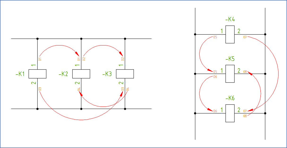
The In and Out fields are directly connected to one visible attribute for each field. For vertical lines, the attribute for In is placed to the left of the line, and the attribute for Out on the right. For horizontal lines, the attribute for In is placed above the line, while the attribute for Out is placed below.
Please refer to the figure below, which shows how the wire-numbers look in circuit diagrams, both vertical and horizontal, as well as how they are interpreted.

Figure 1449: Interpretation of the wire-numbers in the two figures above