|
<< Click to Display Table of Contents >> Non-rectangular boundary boxes |
  
|
|
<< Click to Display Table of Contents >> Non-rectangular boundary boxes |
  
|
cadett ELSA does not directly support non-rectangular boundary boxes, but indirectly it still does. You can use them, and they work excellent. However, a few steps are needed to create them.
Below, you will find an explanation of the entire procedure, with an example showing the creation of a boundary box with six corners, like shown in the figure below.
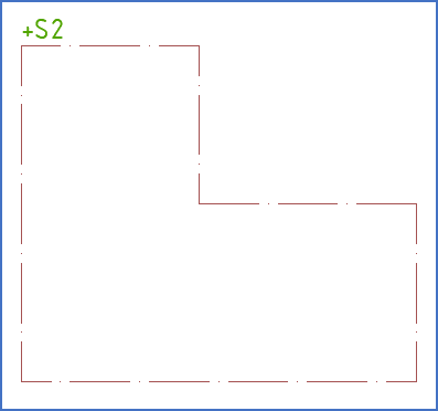
Figure 909: The goal
The following steps need to be taken to create such a six-sided boundary box:
•First you draw two rectangular invisible boundary boxes next to each other, so that they cover the entire area of the intended non-rectangular boundary box. You specify the same plant/location/circuit for both. As has been mentioned above, an invisible boundary box is still visible when Layer setting DESIGN is active. When shifting to a PLOT layer setting, it is however not.
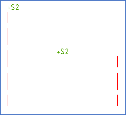
Figure 910: Two invisible boundary boxes next to each other
•Using the LINE command, you draw lines in the BOUNDARY layer along the outer border.
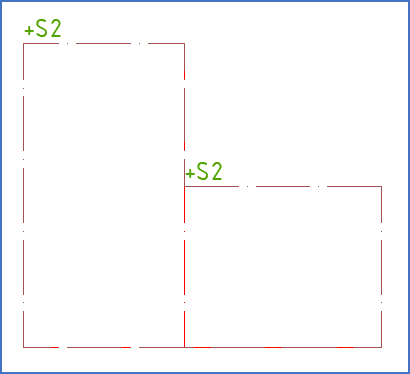
Figure 911: Lines have been drawn in the “BOUNDARY” layer along the outer border. It is somewhat difficult to see here, but the colour
differs slightly.
•Plant/location/circuit are visible in two places, which you probably not wish them to. You make these designations invisible using the Hide attribute command.
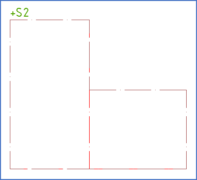
Figure 912: The second "+S2" has been hidden using the "Hide attribute" command.
•To check that the appearance in the final documentation will be as intended, you activate a PLOT layer setting.
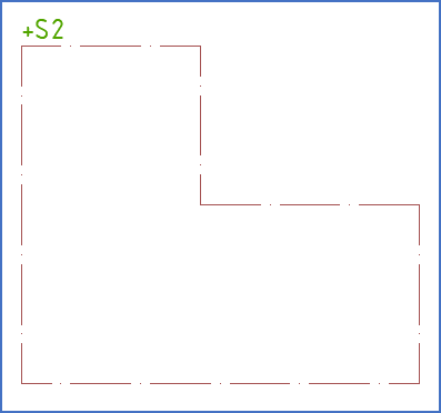
Figure 913: With a PLOT layer setting, the complete non-rectangular boundary box will look like this.
•The result is a boundary box that in all respects both looks and works as required.
•Please do not forget to switch back to Layer setting DESIGN, before continuing the design work.
You must never ever work in a drawing sheet where a PLOT layer setting is active. If you do that anyway, you will run into serious problems.