|
<< Click to Display Table of Contents >> Inserting a cable symbol |
  
|
|
<< Click to Display Table of Contents >> Inserting a cable symbol |
  
|
You insert a cable symbol in the following way:
▪Start by checking that all lines which the cable symbol will be placed on are correctly drawn.
▪In the Symbol Insert Tool, select resource category b – Cables, and there the Cable command. Please refer to the figure above.
▪You are asked if you would like to use the New or the Add option. Select New.
▪Select the first line by clicking “before” that line (to the left if the lines are vertical).
▪Thereafter, select the last line by clicking “after” that line (to the right if the lines are vertical).
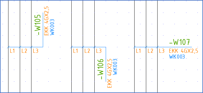
▪Specify how the text should be oriented. The texts that are referred are item designation, index, and electrical data. In a vertical circuit diagram, where you have pointed from left to right, the item designation will be placed to the right of the lines. The texts can be oriented horizontally. To achieve that, click straight to the right. If you instead would like to orient the texts vertically, you click either straight upwards or straight downwards.
Please refer to the figure below for an explanation of the three available options.

Figure 1676: The texts can be oriented in three ways. You can click upwards, downwards, or to the right.
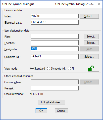
▪The OnLine Cable Main Symbol dialogue box will then be displayed. Here you should specify the item designation of the cable, the index, and the electrical data. Index and electrical data are used to define what kind of a cable it is.

Figure 1677: OnLine Symbol Dialogue Cable main symbol
▪A default item designation will be created automatically, like shown in the figure above. You may of course change that according to your own needs.
▪The index can be entered manually or using the Select… button to the right of the Index field. If you click the Select… button, you will be able to select the index in the Catalogue. In the Catalogue, select the cable type you want to use and then click the Open button. Both the index and the cable type (the electrical data) will then be filled-in automatically. The electrical data might for instance be “EKK4GX2,5” as shown in the figure above.
▪If you type index manually, you will also have to type electrical data manually.
▪In the Cable Main Symbol Dialogue box, you may check and edit additional attributes using the Edit all attributes… button. In that way you can reach some special features. For instance, you can specify the length of the cable in that way.
▪Exit the dialogue box using the OK button.
▪The next question is about the first cable core number. Specify this, for instance “L1”.
▪If you have specified an index of a cable that is defined with a numbering algorithm and a limit in the Catalogue, the default cable core number will automatically be according to the correct numbering of the cable type in question.
Otherwise, the default cable core number will simply be “1”.
▪As the next step, you should specify exactly that (!). That is the “step”. Usually it is “1”, which is also the default. “Step” is the value with which the cable core number is incremented for each new cable core that is inserted.
▪You will then get a question of “Fast insert”.
If you answer Yes, which is also the default, all cable cores will be numbered and inserted without further questions, using the start and step values that you have specified.
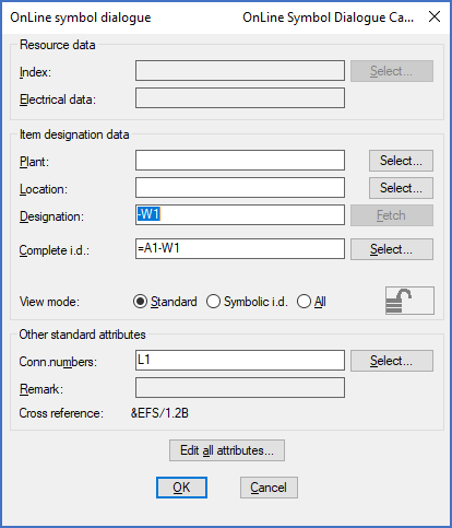
If you on the other hand answer No, one dialogue box for each cable core will be displayed. In that dialogue box, you can adjust the cable core number. Please be sure not to change the item designation in the dialogue box. The item designation must not be changed in the cable core dialogue!

Figure 1678: The Cable Core Dialogue box
In both cases you may change the cable core numbers afterwards.
The “connection number” has already been filled-in. That is simply the cable core number.
▪In the Cable Core Symbol Dialogue box, you can use something called “wire number binding”, which is also reached using the Edit all attributes… button. The possible need for "Wire number binding" is discussed in a sub-topic named Possible problems with cables.
If you wish to insert additional cable cores to the same cable somewhere else in the same drawing sheet or in another sheet, you do that using the same command but with the Add option. The command then works in the same way, but you will not be asked for index, type of cable and similar.