|
<< Click to Display Table of Contents >> Example 1: 1-phase vertical symbol |
  
|
|
<< Click to Display Table of Contents >> Example 1: 1-phase vertical symbol |
  
|
The four figures below shows a simple example of how the AutoLine feature operates. The first figure shows the pre-existing lines between which a simple vertical coil will be inserted.

Figure 1007: This figure shows a simple circuit diagram where a symbol will be inserted with the AutoLine feature ON.
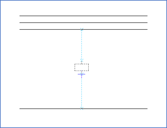
The figure below shows the default situation when the cursor has been moved to the the intended position of the symbol. As you can see, the first possible intersecting line has been chosen, counted outwards from the symbol.

Figure 1008: By default, the automatically created lines will connect to the closest intersecting existing lines.
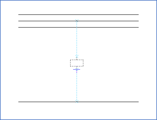
Using the <Up_arrow>, the connection is moved to the next line outwards from the symbol. <SHIFT_Up_arrow> moves the connection in the opposite direction.

Figure 1009: With <Up_arrow> and <SHIFT_Up_arrow>, the connection on the upper side can be moved upwards or downwards. Here, it has been moved upwards.
In this example, it is not possible to move the connection on the lower side of the symbol, for the simple reason that only one possibility exists. If it had been possible, you could have used <Down_arrow> and <SHIFT_Down_arrow> for that purpose.

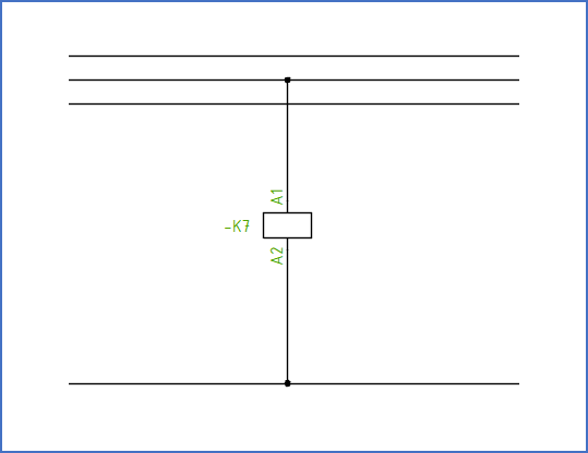
Figure 1010: When everything looks satisfactory, the current position is confirmed with <LEFT_MOUSE_CLICK>. The result will be as shown here.
You confirm the position of the symbol and the suggested lines with a <LEFT_MOUSE_CLICK>. When that has been done, and you are ready with the dialogue box that follows, the result will be as shown in the figure above.
Please refer to the Keyboard commands topic, where all the keyboard commands of the AutoLine feature are listed and explained.