|
<< Click to Display Table of Contents >> Creating a new drawing frame with associated mask |
  
|
|
<< Click to Display Table of Contents >> Creating a new drawing frame with associated mask |
  
|
In this topic, you find a proposal for a practical way to create a new prototype project with a new drawing frame and an accompanied mask. Please note that this is a description of one among many possible ways of getting to that goal.
If you feel unsure about the procedure, it may be a better idea to transfer the job to somebody who do similar things on a regular basis, like cadett. We will be happy to assist you and we can, if you wish, offer a fixed price for the job.
If you would like to do the job yourself, that is even better. Please follow the simple (?!) 63 step process described below.
1.Make sure that Microsoft Windows is configured to NOT hide extensions for known file types. That setting is made in the File Explorer. It will be important later on in the process. To enter the dialogue shown in the figure below, click View, Options and Change folder and search options.
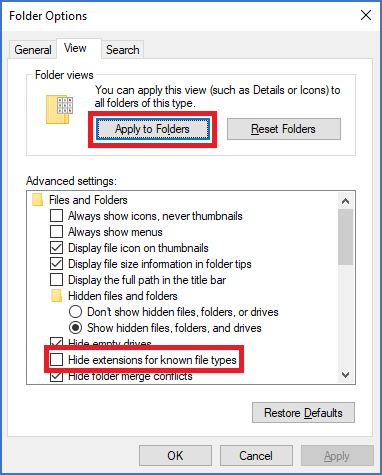
Figure 690: Configuring the File Explorer NOT to hide extensions for known file types
2.Create a new project that you will use to test the new frame and mask. Start from a prototype project that has settings that are as similar to the ones you want to have as possible. Most importantly, the project that you use as prototype should use the drawing frame and mask that you will start with when creating your new drawing frame. Check the project parameters of the new project and make a note of the drawing frame and the mask (or masks) that is uses. You will need that information later.
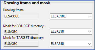
Figure 691: Drawing frame and masks in the project parameters
3.Open the Drawing frames project located in the System group. Activate the Drawing Manager. Click Collect and then Reorganise, not to miss any existing drawing frames.
4.Look for the drawing frame to start with, which should normally be the one that your test project is configured for. It should be as similar as possible to the one that you want to create. ELSA390E is a recommended choice (in English). Corresponding drawing frames in German (ELSA390D) and Swedish (ELSA390S) are also available.
5.Make a copy of the drawing frame that you have decided to start with. (Select it, click Copy, click Paste, confirm the suggested file name, and finally click Reorganise).
6.Rename the new drawing frame to something clever. Keep the name short and simple. Avoid special characters. (Example: MY_OWN). (Click the file name field, edit the content, and click Reorganise).
7.Open the newly created and renamed drawing frame, for example using the Open button.
8.Make the changes that you like to do, considering the guidelines that are discussed in the Drawing frame topic.
Since the drawing frame is made up of blocks, your changes will involve adding new blocks, deleting existing blocks or changing existing blocks.
9.Changing an existing block can be done in several ways. One of them is described here.
10.Find out the name of the block that you want to make changes to. One way of doing that, is to use the LIST command, which is located in the Drawing aids tab of the ribbon menu, in the Tools slide-out panel.
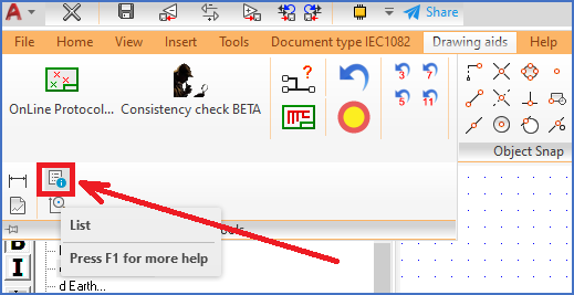
Figure 692: The LIST command in the ribbon menu
The name could for example be RITRAM (the name of the main block of the ELSA390E drawing frame).
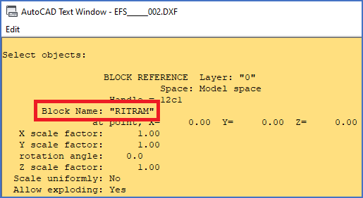
Figure 693: The LIST command is very useful to get detailed information about selected objects, like blocks.
11.Save the block in question as a DWG file with the same name as the block and located in the workstation directory, using the WBLOCK command, as described below.
12.Select the WBLOCK command in the menu, for example from the Insert tab of the ribbon menu, more precisely the Block Handling panel, as shown in the figure below.

Figure 694: The WBLOCK command in the ribbon menu
Command: --- WBLOCK WITH INSERT ---
Local directory : "C:\ELSAWS0\"
Global directory: "C:\ELSA\SYMBOLE\IEC1082\"
Save Locally/Globally/Specified/<eXit>: L
INSERT after WBLOCK (Y/<N>): N
File name: RITRAM
Block name: RITRAM
13.A DWG file with the specified name (RITRAM.DWG in the example) is thus created.
14.As next step, please open the DWG file for editing. Use the OPEN command to do so. Do not save the current DXF file in any way.
The OPEN command can be reached from the File tab of the ribbon menu, more precisely the File slide-out panel, as shown in the figure below.
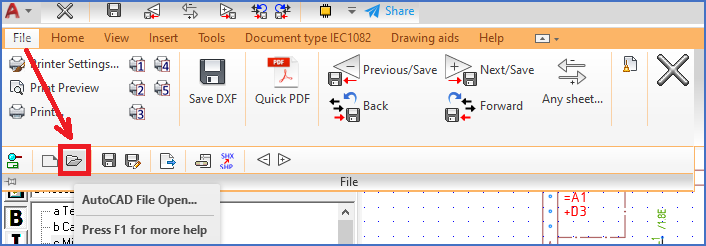
Figure 695: The OPEN command in the ribbon menu
Answer No to the question of saving the DXF file. Then you might have to manually navigate to the current workstation directory, typically named and placed like C:\ELSAWSxxxx or similar. Select the newly created DWG file and click Open.
15.The content of the block will then be editable, as if the block had been exploded, which it has not. You can then make any changes that you like, both to attributes and graphics such as lines.
Pay attention to layers and line types, when you make your changes.
16.Consider previously given advice regarding attribute (tag) names. Keep them identical with the standard frame as far as possible. Choose a name with "Z" as the first letter and then a simple abbreviation of the use of the field. Avoid characters other than A-Z, 0-9, and underscores ("_") in attribute names.
You can adjust attribute names using the standard cadett ELSA DDATTE/ATTEDIT command. With that command, you can also adjust the prompt used in the attribute dialogue that is displayed when editing the title field within the Drawing Environment.
You can type EA in the command line to access that command, or select it in the the Text and Attributes panel of the Home tab of the ribbon menu.
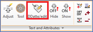
Figure 696: The DDATTE/EDIT command
Pay attention to text height, text justification and layers. Primarily use the standardized text heights of 1.8, 2.5, 3.5 and 5.0 mm. Place the attributes in the corresponding layers, TXT18, TXT25, TXT35 and TXT50. Use text justifications (left, right, centred, midpoint) that keep all occurring values within each field.
You can easily change both text justification and rotation as well as position of an attribute using the Adjust Text and Attributes command, located two positions to the left of DDATTE/EDIT shown in the figure above.
You can change the text height and also all other properties of an attribute with the PROPERTIES command. That command is not available in the menus, so you have to type it in the command line. (The reason for its absence in the menu is the limited OnLine support that it offers).
17.When the content of the block is satisfactory, you save it using the SAVE command, which will save it to the DWG file. The SAVE command is found in the File slide-out panel of the File tab of the ribbon menu.
18.Exit the drawing. DO NOT SAVE when doing so.
19.Back in the Drawing Manager, open the new drawing frame once again.
20.The changes that you made to the block will then NOT be visible.
21.Check the insertion point and the layer of the block that you changed. You can do that using the LIST command, mentioned before.
22.Delete the block using the ERASE command, located in the Modify panel of the Home tab of the ribbon menu.
23.Using the INSERT command, insert the new version of the block. The name must be followed by an equal sign. Otherwise you will get the old version of the block once again. Pay attention to the insertion point. Also pay attention to the layer in which you insert the block. Adjust if needed.
The INSERT command can be accessed in the Block Handling panel of the Insert tab of the ribbon menu.

Figure 697: The INSERT command
24.Save the changes that you have made using the Save DXF command located in the File tab of the ribbon menu.
25.Repeat the procedure for other blocks that need adjustments.
26.When it comes to plant, location, and sheet number, and additionally document number, DCC code, circuit/product and some others, they constitute special cases. They must not be included in the large block or blocks that make up the frame. They are separate blocks and should remain so.
Please refer to the Drawing frame topic for a more detailed description of the requirements for those blocks.
27.Consider the advise given in the Drawing frame topic regarding text style. Preferably use cadett ELSA's standard text style (STANDARD). The active text style (STYLE) should in any case be named STANDARD and refer to an ISO font, preferably ISOCPEUR.TTF, ELISO.SHX or ISOCP2.SHX.
28.The best choice in most respects, is to use a Truetype font, preferably ISOCPEUR.TTF.
29.Make a note of all changes related to block names and tag names. You will need that information later.
Using the LIST command, it is easy to obtains that information. To have the information easily accessible, you can print it. Use the LIST command and select all changed drawing frame blocks (one or more). The information about all attributes is shown in the text window which you display using the <F2> key. Press <RETURN> for each new text page until all information has been displayed and you are back at the command prompt.
30.Select all relevant information in the text window and copy it with <CTRL_C>.
31.Start a simple text editor such as Notepad. Paste the text there with <CTRL_V>. Print if you prefer to have the information on paper. Otherwise, simply save it as a text file.
32.Leave the drawing environment with the EXIT command.
33.The new drawing frame is then ready for testing.
34.The turn has then come to the mask. You must define a mask and an associated mask file that fits the new
drawing frame.
Based on the mask file, the Drawing Manager creates the Drawing Manager database.
35.Activate the Settings module and the Masks tab.
36.Select the mask to start with, as you made a note of in the beginning of this process. Here we assume that you start with the ELSA390 mask. Click the Open button. Editing of the associated mask file (ELSA390.MSK in the example) in Notepad then starts.
37.Immediately select Save As in the File pull-down menu of Notepad. Give the new mask file an appropriate name, for example MY_OWN.MSK.
38.Exit Notepad using the Exit command in the File pull-down menu.
39.You have then created a new mask file - MY_OWN.MSK in the example - which is a pure copy of the one you started with (ELSA390.MSK in the example).
40.The next step is to attach a new mask to this mask file. To do so, click the New button. Enter a suitable mask name, preferably the same as the mask file name (MY_OWN in the example). Enter a description and a signature. Use the browse button to the right of the mask file field to select the newly created mask file. Click OK. The new mask is created and you can see it in the mask list.
41.Select the new mask. Open it with the Open button.
42.Modify the mask file so that it matches your newly created drawing frame.
Do not forget to update the comments in the beginning of the mask file, with file name, originator, date and similar.
The link between a field in the Drawing Manager and an attribute in the title field is defined either using block name and tag name, or using the coordinates of the attribute. Block and tag names are recommended whenever nothing prevents you from using them, since they are quicker and easier to define and therefore reduces the risk of annoying mistakes.
Please note that the order between the rows in the mask file is of great importance. It defines the order in which the cursor moves between the fields in the detailed view when you use the <TAB> key. In addition, it controls the order between the columns in the survey, even if it is possible to override that directly in the Drawing Manager.
43.The structure of the mask file is described in detail in comments at the beginning of the ELSA390.MSK, of which your own mask file is now a copy (in the example, that is). More detailed descriptions of all mask file syntax and format details are found in the Mask file details topic.
44.Save the mask file when done.
45.Adjust the project parameters of your test project, by changing the Mask for both the SOURCE and the TARGET directories to your newly created one. Then change the Drawing frame to the one that you have created. (Please refer to the Drawing frame and mask sub-topic of the Project Module topic).
46.Open the test project, and activate the Drawing Manager.
47.In order for the changes that you have made to the mask file to take effect, in the Module pull-down menu, first select Mask file / Reread central MSK file (SOURCE), and then Mask file / Reread central MSK file (TARGET).
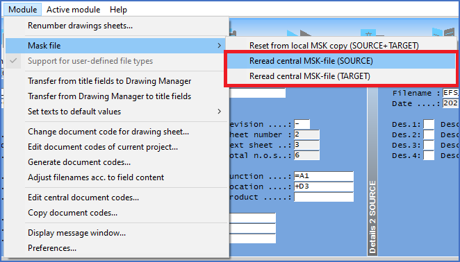
Figure 698: The "Reread central MSK file" commands
48.Check the detailed view(s) in the SOURCE directory. If something looks wrong, you can adjust the mask file, and run the Mask file / Reread central MSK file commands once again.
49.Create two new drawing sheets using the New command. (There are several reasons for creating two, not one, sheets at this stage).
50.Using the Viewer, check that it is fact your new drawing frame that has been used. If not, make the necessary adjustments wherever they are needed.
51.Fill in all positions in the detailed view for the first sheet. Open the drawing sheet using the Open button in the toolbar.
52.Check all texts in the title field. If something is not correct, you can change the mask file, run the Mask file / Reread central MSK file commands once again, and then try the communication again.
53.In the Drawing Environment, modify all texts in the title field. Exit the drawing sheet with the EXIT command. When doing so, confirm that the drawing sheet should be saved.
54.Check the content of the detailed view in the Drawing Manager. If any texts have not been transferred correctly, you can adjust the mask file, reread the mask files once again, and then retry the communication.
55.When you are satisfied with the design of the detailed views, with the design of the drawing frame and the title field, and last but not least with the communication between them, you begin to approach a finished result. However, you are not really there yet!
56.The last thing that needs to be done, is to create a new prototype project.
57.Continue with the test project and adjust all project parameters to cover all needs that you have for your future projects. Verify that everything works as intended, for example when it comes to item designations, cross-references, attribute mirroring, electrical layers, and other features.
58.If necessary, check and adjust the block name of the main block for the drawing frame. Please refer to the Project Module topic, the Block name for title field sub-topic.
59.Correct the parameters of the Drawing Manager to match the new drawing frame. In particular the parameters that define column and row division, and electrical layers, must match the details of the new drawing frame. Please refer to the Drawing Manager 2 tab of the Project Parameters in the Project Module.
60.With the test project as prototype, create a new empty project which will constitute your new prototype project. (You can also delete all drawing sheets in the test project and then turn it into the new prototype project).
61.Make sure that the new prototype project is located in a group that is suitable as default for new projects and that the name of the project makes it easy to identify.
62.In the Basic preferences tab of the Project Parameters, check Prototype project in the Additional project settings section, so that the new prototype project is displayed in the virtual Prototype projects group.
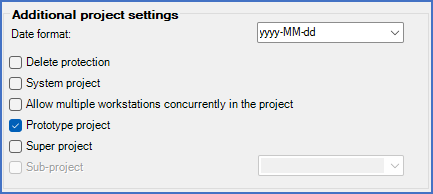
Figure 699: The project is turned into a prottype project.
63.You then have a prototype project with the new drawing frame and the associated mask and mask file. Use it as a starting point for new projects. You will find your new prototype project in the virtual Prototype projects group, in the same place as the standard prototype projects that are included in the delivery of cadett ELSA.
With that, the new prototype project is ready to use!