|
<< Click to Display Table of Contents >> How to insert PLC symbols |
  
|
|
<< Click to Display Table of Contents >> How to insert PLC symbols |
  
|
The PLC symbols are inserted using the Symbol Insert Tool.
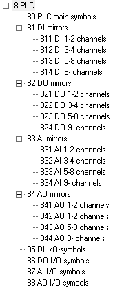
Resource category 8 is used for PLC symbols, and contains suitable sub-categories to make it easy to find and select desired PLC symbols.
All PLC resource categories are shown in the picture below.

Figure 1050: Resource Categories for PLC symbols
Please note that the I/O symbols are available in both Vertical and Horizontal versions, while the PLC mirrors are supplied in Horizontal versions only.
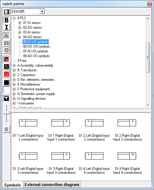
In the Symbol Insert Tool the PLC symbols are presented as shown in the picture below.

Figure 1051: PLC symbols in the Symbol Insert Tool. (Example: category 85).
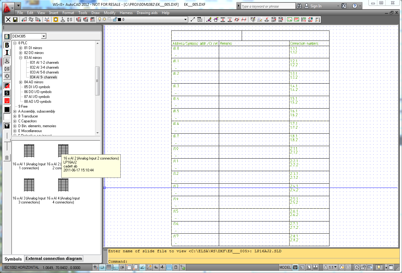
Please note that full-screen previews are available for all PLC symbols. This is especially useful for the PLC mirrors which are relatively complex.

Figure 1052: A PLC mirror with 16 analogue inputs with 2 connections each is being selected in the Symbol Insert Tool. Please note the full-screen preview!