|
<< Click to Display Table of Contents >> Wire list |
  
|
|
<< Click to Display Table of Contents >> Wire list |
  
|
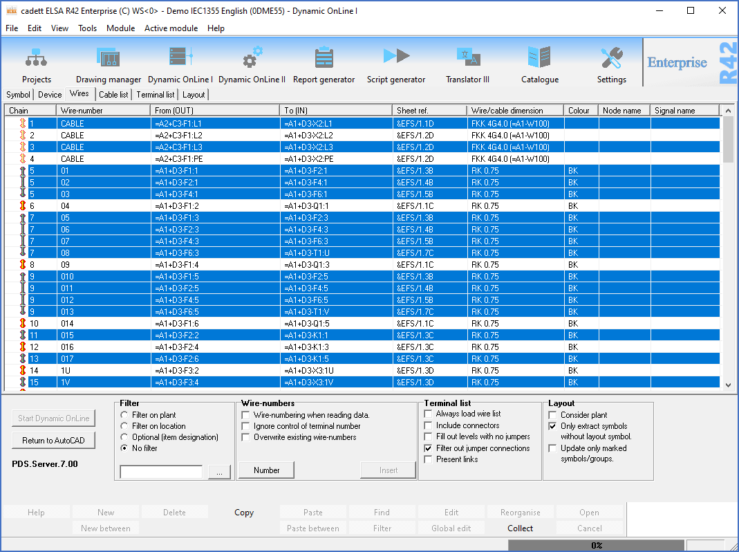
The Wire list in Dynamic OnLine I shows, in principle, the same information as a conventional internal wire list. However, all connections are displayed here, both internal and external, and both wires and cables.

Figure 1145: The Wire list in Dynamic OnLine I
cadett ELSA makes no principled distinction between external and internal connections. A connection between two locations are normally regarded as "external", as opposed to a connection within the same location, which is therefore "internal".
On the other hand, “cables” are separated from wires.
•A “cable” is often associated with a cable definition in the catalogue, like EKK3X1.5. In many cases, cables are synonymous with external connections, but that is only part of the truth, since you might have internal cables, as well as external wires.
•The opposite is a conventional single wire, like a RK1.5. This is often synonymous with internal connections, but that too is only part of the truth, for the same reasons as stated above.
Note
External connections are commonly defined as connections between locations (like cabinets), while internal connections in the corresponding way are defined as connections within a location (for example a cabinet).
Connections which are cores of cables are marked in the circuit diagram with special cable symbols that specify which cable they belong to, and which cable core number they have. Connections which are not marked with such cable symbols are interpreted as common single wires.
Wires, in some cases somewhat carelessly called “internal connections”, can be numbered. These numbers are referred to as “wire-numbers”.
The wire-numbers are inserted in the circuit diagram manually, automatically or in a combination of both. There are several good reasons to insert wire-numbers in the circuit diagram, among others that they must be saved somewhere, and the circuit diagram is the best place for that. This is for example a prerequisite to correctly handle any future revisions.
Wire-numbers are stored in special, for the purpose intended symbols, wire-number symbols, which are placed on the connection points of a symbol. Besides from wire-numbers, these symbols can also contain properties such as dimension, colour, node name and signal name.
Another important function which the wire-number symbols have, is to define the wiring sequence, meaning how the wires should be connected physically. This is something that the circuit diagram otherwise does not show. The circuit diagram specifies what is connected to what, but not how. The wire-numbers change that! A side effect of this is that the wire-number symbols serve as a container for other properties of the wires, like colour and dimension.
In a project without any wire-number symbols, cadett ELSA can still present a complete Wire list, without any problems what-so-ever. So, how can that be possible?
In that case, the Wire list is built upon assumptions about the wiring sequence. These assumptions are made in a way that tries to optimise the wiring in the best possible way, given the information that is available to the program. Optimising the wiring means that the program tries to find the shortest possible path in a physical sense. The information that is available is used to – as far as possible – calculate the best wiring sequence. Information that can be used for that purpose include any possible cabinet layout, location designations, plant designations, component type letter codes, item designations as a whole, and connection point numbers.
The Wire list, which is calculated in this way, is completely unnumbered. It exists only in the memory, and is therefore volatile. It will disappear if you close the program. By performing a numbering of the wires in the list, which can be done automatically, and then inserting the wire-numbers in the circuit diagram, the information is saved. Thereafter, you will have a great starting point from which you can introduce any changes, whether that regards the wiring order, the numbering or other wire properties such as dimensions or colours.
Many times, this automatic analysis results in a completely satisfying Wire list, at least in most parts. Some adjustments may be required to make the critical designer pleased, but in many cases that will be limited to minor modifications. That work does not need to be done again.
How Dynamic OnLine should create the original unnumbered Wire list, meaning what the program should take into consideration and what to ignore, is controlled partly by the project parameters. How the wire-numbering itself should be done, meaning which numbers to use, is also controlled by the project parameters.
A lot can be said about this and you can read about all the details partly in the detailed description of wire-numbering in cadett ELSA, which you will find in the sub-topic named Wire-numbering in cadett ELSA, and partly in the description of the involved project parameters in the Project module topic, sub-topic Connections 2 tab.
Please note that changes which you make in the Wire lists are not transferred directly to the circuit diagram in the way that is done for the Symbol list or the Device list. Here you are instead required to issue a command to transfer your changes to the drawing sheets.
For more information, please refer to the following sub-topics:
•Wire-numbering in cadett ELSA
•Presentation of the wire list
•Rearrange the wires of a chain
•Handling of errors in the wire list