|
<< Click to Display Table of Contents >> Settings |
  
|
|
<< Click to Display Table of Contents >> Settings |
|
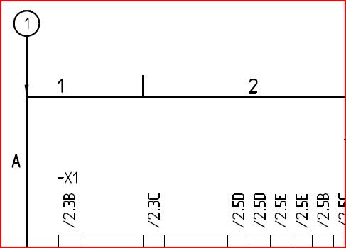
A KABGRAF II configuration is extensive and only a part of it fits the screen at a time. You use the drag list in the right side of the palette to move up or down among all the parameters.

Figure 1488: The settings are extensive. Move up or down using the drag list.
The table below describe the parameters in full detail.
Name and description |
||
Name |
Name of the configuration. This name is also used as the filename of the KABGRAF file in which the configuration is stored. |
|
Description |
A description in plain text of the configuration in question. |
|
Coordinates and sizes |
||
x-coordinate for left side of drawing frame |
x-coordinate for the border of the drawing area to the left, in most cases the vertical line that limits the drawing area on the left side.
|
|
x-coordinate for right side of drawing frame |
x-coordinate for the border of the drawing area to the right, in most cases the vertical line that limits the drawing area on the right side.
|
|
y-coordinate for top symbols |
y-coordinate for the insertion points of the symbols on the upper side of the external connection diagram.
|
|
y-coordinate for bottom symbols |
y-coordinate for the insertion points of the symbols on the lower side of the external connection diagram.
|
|
x-coordinate for start of diagram |
x-coordinate for the insertion point of the first symbols (the ones furthest to the left) in both the upper and the lower side of the diagram.
Please note that the insertion point for these symbols is located in the middle from a horizontal perspective. The consequence is that the graphical beginning is found on a somewhat lower x-coordinate than the one specified here, depending on the graphical appearance of the symbol.
|
|
Width of diagram |
Distance in the x-direction between the insertion points of the first and the last possible symbols.
Please note that the insertion points of these symbols are located in the middle of them and that the true graphical width of the diagram therefore is greater than what this parameter might imply, this fact unconsidered.
|
|
x-distance between symbol insertions |
The width of the symbols (size in x-direction).
|
|
y-distance between levels |
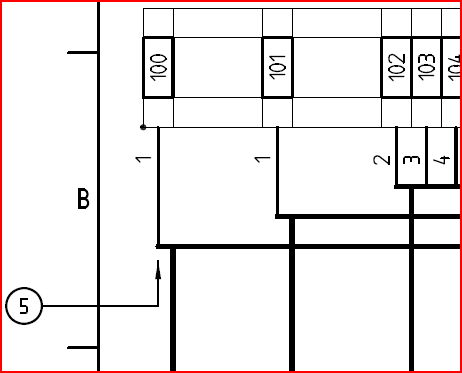
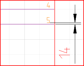
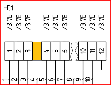
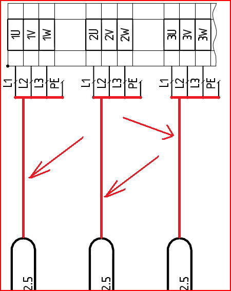
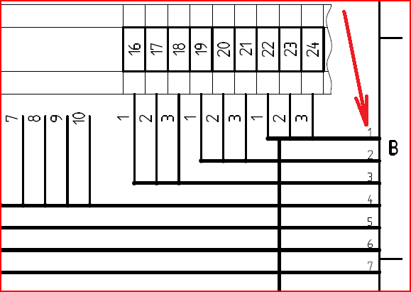
When cables cross each other, of which an example is shown in the picture above, this is shown with horizontal lines in separated levels, meaning separated vertically. This parameter determines the distance between these horizontal lines in the y-direction.
|
|
Half the cable balloon height |
Half the height of the cable balloon, meaning how far vertically from the insertion point in the middle that the upper and lower borders of the symbol are located.
The insertion point of the cable balloon should be located in the middle both in the x and y directions. This means that this parameter actually defines the distance in y between the insertion point and the vertical lines that is connecting to the balloon.
|
|
Height of symbols |
The vertical size of the symbols in the upper and lower side of the diagram.
|
|
Minimal group count. If smaller an extra gap is created. |
This parameter is used to avoid the diagram from being to tight in three different ways:
-Distance between groups -Distance between terminal groups -Distance between cable balloons
Conventional devices and PLC’s are treated in the same way as terminal groups when this parameter is concerned.
Common value: 3.
If the diagram would be too tight, symbols might end up partly overlapping one another, resulting in poor visibility.
If for example the cable balloon would be bigger than the one that is included in the delivery a greater distance between them is required to avoid conflicts. This can be achieved by increasing the value of this parameter.
|
|
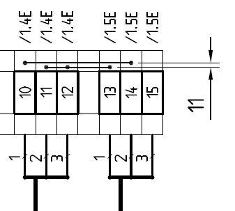
Distance between jumper levels |
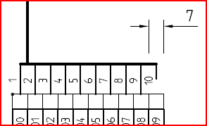
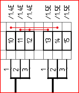
Vertical distance between parallel jumpers. Up to four jumpers in parallel at each side of the terminal are supported.
|
|
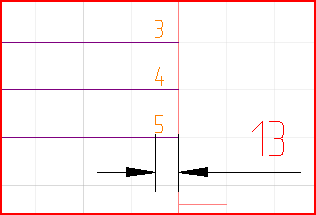
Text height for level reference text |
When a group is so big that it must be divided between pages horizontal lines will pass between pages. Level references are used to enhance visibility for where such a line continues on the nest sheet.
The text height of such a level reference is defined here.
|
|
x-offset for level reference text |
Distance in the x-direction from the end of the horizontal line.
|
|
y-offset for level reference text |
Distance in the y-direction from the end of the horizontal line.
|
|
Draw donut on cable connections |
A connection point can be drawn where cables diverse as an extra clarification. Here you define if that is going to be made or not.
|
|
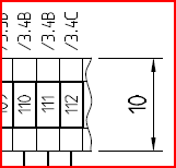
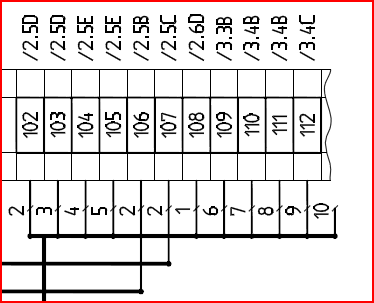
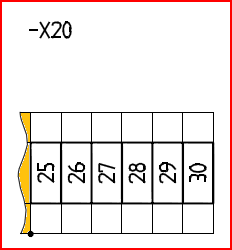
Remove terminals without connections in groups bigger than one
|
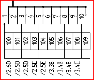
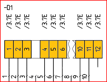
Unconnected terminals, like spare terminals, can be omitted from terminal groups that contain more than one terminal if desired. They are then replaced with symbols showing that an omitting has been made.
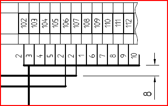
In the picture above terminals 113 and forward have been omitted because they are not connected.
|
|
Show spare cable cores |
PE in the picture above is a spare cable core. It is defined using an algorithm or a cable mirror but is not drawn in the circuit diagram.
|
|
Show spare terminals |
Spare terminals are terminals which are not connected in any way. In many cases they are not drawn in the circuit diagram either. Instead they are defined by an algorithm.
Terminal 109 in the picture above is such an example. Please note that a cross-reference is missing since no corresponding symbol in the circuit diagram exists.
|
|
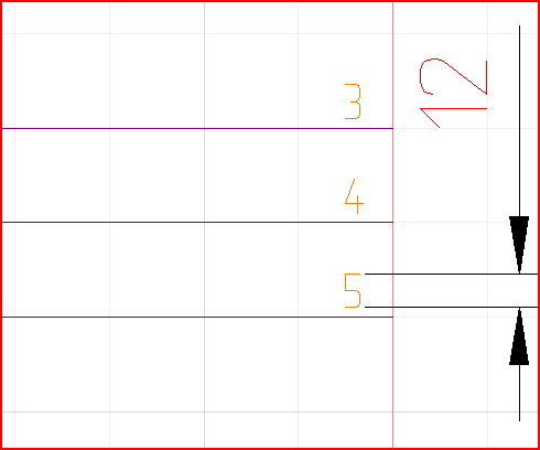
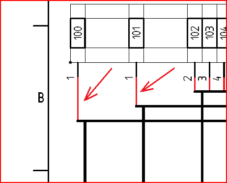
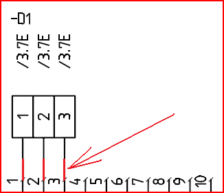
Show level reference numbers |
When a group is so big that is must be divided between sheets, horizontal lines will pass between the sheets. Level references will be used to clarify where such a line continues on the next sheet.
Here you define whether level reference numbers should be used or not.
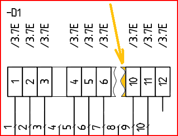
The red arrow in the picture above points at a level reference number.
|
|
Output |
||
DXF form |
Filename of the DXF form that should be used. A standard form for this purpose is included at delivery:
-0EEMB005.DXF
|
|
Output filename |
The naming of generated files is defined here using a code.
Example: TG___%03i.DXF
This code can be divided in the following parts:
|
|
TG___ |
Each filename begins with this character combination. |
|
%0 |
The digit zero should be used to fill the counting numbers to the desired length. |
|
3 |
Fill to this number of characters. |
|
i |
Integer. |
|
.DXF |
Each filename is ended with this character combination. Constitutes the file type. |
|
Result:
TG___001.DXF, TG___002.DXF, TG___003.DXF ans so on.
|
||
File delete mask |
Before the external connection diagram is generated, all files according to the specified file delete mask are deleted. The intention is to delete the previous version of the external connection diagram.
Example: TG___*.DXF
|
|
Directory |
Here you can choose if the generated external connection diagram should be placed in the SOURCE or in the TARGET directory.
If you place it in the TARGET directory it will “be OnLine” which means that you will automatically get cross-references to the circuit diagrams and that changes made to item designations using Dynamic OnLine or similar, will automatically update the external connection diagram as well. Please be careful with the filename and file delete mask specifications so that you won’t accidentally delete or overwrite precious circuit diagram sheets or other files that you wish to preserve.
If you place the external connection diagram in the TARGET directory, you do not have to worry about overwriting anything valuable, but you lose all OnLine functionality, including cross-references.
|
|
Terminals and connectors |
||
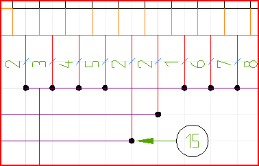
Up first |
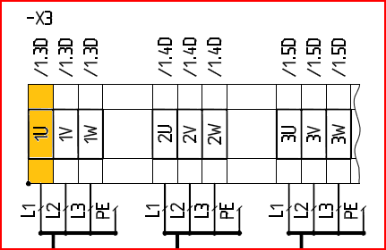
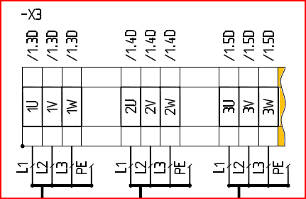
Symbol name for terminals on the upper side (the first terminal in each group). Should normally be defined as a terminal help symbol with visible terminal group name.
The symbol above that is shown in yellow colour is an example of this symbol. Here it has a visible terminal group name.
|
|
Up second |
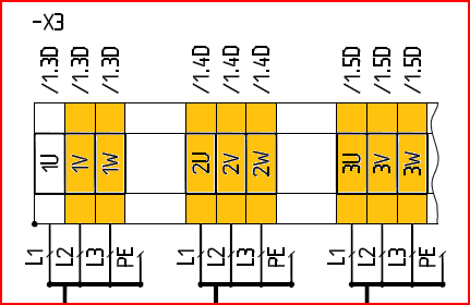
Symbol name for terminals on the upper side (all terminals except the first one in each group). Should be defined as a terminal help symbol with invisible terminal group name.
The symbol above that is shown in yellow colour is an example of this symbol. Here it has an invisible terminal group name.
|
|
Up space |
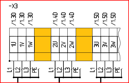
Symbol name on the upper side for gaps between terminals that is inserted when terminals are displaced sideways to enhance the visibility of the diagram. Should be defined as a non-electric symbol.
The symbols that are shown in yellow colour in the picture above are examples of this symbol. Please note that the width of the symbol in question is equal to the width of the terminal symbol. This means that the picture above actually shows four such symbols in two groups of two symbols each.
|
|
Up right split |
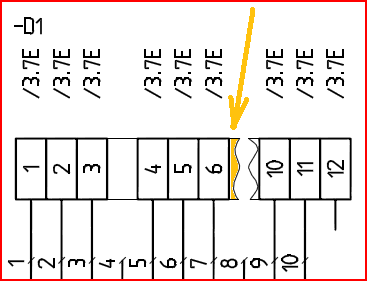
Symbol name on the upper side which symbolises that terminals have been omitted in order to enhance the visibility of the diagram. Shows that terminals to the right of the current position have been omitted. Should be defined as a non-electric symbol.
An example of this symbol is shown in yellow colour in the picture above.
|
|
Up left split |
Symbol name on the upper side which symbolises that terminals have been omitted in order to enhance the visibility of the diagram. Shows that terminals to the left of the current position have been omitted. Should be defined as a non-electric symbol.
An example of this symbol is shown in yellow colour in the picture above.
|
|
Down first |
Name of symbol for terminals on the lower side (first terminal in each group). Should be defined as a terminal help symbol with visible terminal group name.
Please refer to the corresponding symbol on the upper side above.
|
|
Down second |
Symbol name for terminals on the lower side (all terminals except the first one in each group). Should be defined as a terminal help symbol with invisible terminal group name.
Please refer to the corresponding symbol on the upper side above.
|
|
Down space |
Symbol name on the lower side for gaps between terminals that is inserted when terminals are displaced sideways to enhance the visibility of the diagram. Should be defined as a non-electric symbol.
Please refer to the corresponding symbol on the upper side above.
|
|
Down right split |
Symbol name on the lower side which symbolises that terminals have been omitted in order to enhance the visibility of the diagram. Shows that terminals to the right of the current position have been omitted. Should be defined as a non-electric symbol.
Please refer to the corresponding symbol on the upper side above.
|
|
Down left split |
Symbol name on the lower side which symbolises that terminals have been omitted in order to enhance the visibility of the diagram. Shows that terminals to the left of the current position have been omitted. Should be defined as a non-electric symbol.
Please refer to the corresponding symbol on the upper side above.
|
|
PLC |
||
Up first |
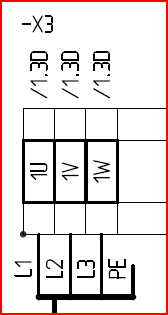
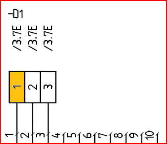
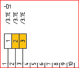
Name of symbol for PLC connections on the upper side (the first connection in each group). Should be defined as a PLC help symbol with function code KABGRAF and with visible item designation.
The symbol that is shown in yellow in the picture above is an example of this symbol.
|
|
Up second |
Symbol name for PLC connections on the upper side (all connections except the first one in each group). Should be defined as a PLC help symbol with function code KABGRAF and with invisible item designation.
The two symbols that are shown in yellow in the picture above are examples of this symbol.
|
|
Up space |
Symbol name on the upper side for a space between connections that is used when the connections are spread sideways to increase the readability of the diagram. Should be defined as a non-electric symbol.
The symbol that is shown in yellow in the picture above is an example of this symbol.
|
|
Up right split |
Name of symbol on the upper side symbolizing that connections have been omitted to increase the readability of the diagram. Shows that connections to the right of the current position have been omitted. Should be defined as a non-electric symbol.
Also used to show that the PLC continues on the next sheet when applicable.
The symbol that is shown in yellow in the picture above is an example of this symbol.
|
|
Up left split |
Name of symbol on the upper side symbolizing that connections have been omitted to increase the readability of the diagram. Shows that connections to the left of the current position have been omitted. Should be defined as a non-electric symbol.
Also used to show that the PLC continues from the previous sheet when applicable.
The symbol that is marked with yellow in the picture above is an example of this symbol.
|
|
Down first |
Name of symbol for PLC connections on the lower side (first connection in each group). Should be defined as a PLC help symbol with function code KABGRAF and with visible item designation.
Please refer to the corresponding symbol on the upper side above.
|
|
Down second |
Name of symbol for PLC connections on the lower side (all connections except the first one in each group). Should be defined as a PLC help symbol with function code KABGRAF and with invisible item designation.
Please refer to the corresponding symbol on the upper side above.
|
|
Down space |
Symbol name on the lower side for a space between connections that is used when the connections are spread sideways to increase the readability of the diagram. Should be defined as a non-electric symbol.
Please refer to the corresponding symbol on the upper side above.
|
|
Down right split |
Name of symbol on the lower side symbolizing that connections have been omitted to increase the readability of the diagram. Shows that connections to the right of the current position have been omitted. Should be defined as a non-electric symbol.
Also used to show that the PLC continues on the next sheet when applicable.
Please refer to the corresponding symbol on the upper side above.
|
|
Down left split |
Name of symbol on the lower side symbolizing that connections have been omitted to increase the readability of the diagram. Shows that connections to the left of the current position have been omitted. Should be defined as a non-electric symbol.
Also used to show that the PLC continues from the previous sheet when applicable.
Please refer to the corresponding symbol on the upper side above.
|
|
Conventional devices |
||
Up first |
Name of symbol for connections to conventional devices on the upper side (the first connection in each group). Should be defined as a conventional help symbol with function code KABGRAF and with visible item designation.
Please refer to the corresponding symbol for PLC’s above.
|
|
Up second |
Symbol name for connections to conventional devices on the upper side (all connections except the first one in each group). Should be defined as a conventional help symbol with function code KABGRAF and with invisible item designation.
Please refer to the corresponding symbol for PLC’s above.
|
|
Up space |
Symbol name on the upper side for a space between connections that is used when the connections are spread sideways to increase the readability of the diagram. Should be defined as a non-electric symbol.
Please refer to the corresponding symbol for PLC’s above.
|
|
Up right split |
Name of symbol on the upper side symbolizing that connections have been omitted to increase the readability of the diagram. Shows that connections to the right of the current position have been omitted. Should be defined as a non-electric symbol.
Also used to show that the device continues on the next sheet when applicable.
Please refer to the corresponding symbol for PLC’s above.
|
|
Up left split |
Name of symbol on the upper side symbolizing that connections have been omitted to increase the readability of the diagram. Shows that connections to the left of the current position have been omitted. Should be defined as a non-electric symbol.
Also used to show that the device continues from the previous sheet when applicable.
Please refer to the corresponding symbol for PLC’s above.
|
|
Down first |
Name of symbol for connections to conventional devices on the lower side (first connection in each group). Should be defined as a conventional help symbol with function code KABGRAF and with visible item designation.
Please refer to the corresponding symbol for PLC’s above.
|
|
Down second |
Name of symbol for connections to conventional devices on the lower side (all connections except the first one in each group). Should be defined as a conventional help symbol with function code KABGRAF and with invisible item designation.
Please refer to the corresponding symbol for PLC’s above.
|
|
Down space |
Symbol name on the lower side for a space between connections that is used when the connections are spread sideways to increase the readability of the diagram. Should be defined as a non-electric symbol.
Please refer to the corresponding symbol for PLC’s above.
|
|
Down right split |
Name of symbol on the lower side symbolizing that connections have been omitted to increase the readability of the diagram. Shows that connections to the right of the current position have been omitted. Should be defined as a non-electric symbol.
Also used to show that the device continues on the next sheet when applicable.
Please refer to the corresponding symbol for PLC’s above.
|
|
Down left split |
Name of symbol on the lower side symbolizing that connections have been omitted to increase the readability of the diagram. Shows that connections to the left of the current position have been omitted. Should be defined as a non-electric symbol.
Also used to show that the device continues from the previous sheet when applicable.
Please refer to the corresponding symbol for PLC’s above.
|
|
Cables |
||
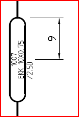
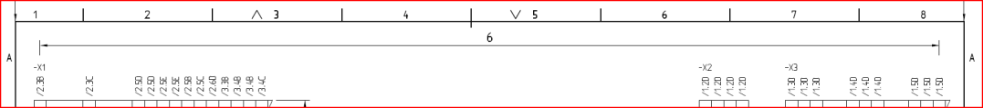
Balloon |
The name of the symbol that should be used for the cable balloon. A user defined symbol can be used. The symbol should be defined as a cable help symbol without connection, that is a cable help symbol that is not a cable core.
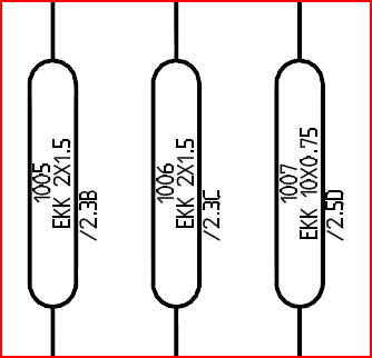
The picture above shows three examples of the symbol in question.
|
|
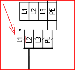
Up |
Name of the symbol that should be used for the cable cores on the upper side. A user defined symbol can be used. The symbol should be defined as a cable help symbol without connection, that is a cable help symbol that is not a cable core in its original meaning.
The symbol within a red box in the picture above is an example of this symbol.
|
|
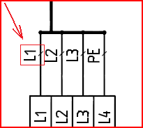
Down |
Name of the symbol that should be used for the cable cores on the lower side. A user defined symbol can be used. The symbol should be defined as a cable help symbol without connection, that is a cable help symbol that is not a cable core in its original meaning.
The symbol within a red box in the picture above is an example of this symbol.
|
|
|
||
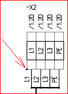
External side mark |
Symbol that is inserted on the external side of terminals to show the direction.
In the picture above a yellow arrow is pointing at the symbol in question. Graphically in that case the symbol is a filled circle.
|
|
Layers |
||
Cable core line |
Layer where vertical lines that symbolize cable cores are drawn. Should be a non-electric layer.
In the picture above the lines in question are showed in red colour.
|
|
Cable core |
Layer where the cable core symbols are inserted. Should be an electric layer.
The picture shows the symbol in question.
|
|
Cable line |
Layer where lines that symbolizes the cable as a whole is drawn. Should be a non-electric layer.
In the picture above the lines in question are shown in red colour.
|
|
Cable |
Layer where the cable balloon symbols are inserted. Should be an electric layer.
The picture above shows the symbols in question.
|
|
Symbol |
Layer where symbols for terminals and devices are inserted. Should be an electric layer.
Examples of symbols that are affected by this parameter are shown in yellow colour in the picture above.
|
|
Symbol connection |
Layer where vertical lines symbolizing the connections are drawn. Should be a non-electric layer.
The lines in question are shown in red colour in the picture above.
|
|
Jumpers |
Layer for jumpers. The layer should be non-electric.
Examples of jumpers are shown in red colour in the picture above.
|
|
Level reference text |
This should be a non-electric layer adapted to the selected text height. For a text height of 1.8 mm the TXT18 layer is for example a good choice.
The picture above shows an example of level reference text.
|
|
Attribute filling |
||
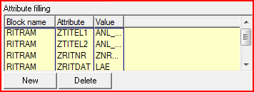
These parameters are used primarily to automatically fill in the information of the title field, but the functionality is general enough to be used for many other purposes as well. To put it shortly, information from any project parameters can be transferred to any attributes of any blocks in the external connection diagram that is being created.
Below you will find a description of both the parameters and the editing tools for these settings.
Each line in the table corresponds to one attribute.
|
||
Columns in the table |
||
Block name |
Name of the block in which the attribute to which data is going to be transferred is located. It can for example be the main block of the drawing frame.
|
|
Attribute |
Name of the attribute to which data is going to be transferred.
|
|
Value |
Field name for the project parameter which data is going to be fetched from. In most cases this is field names of PROJECTS.DBF or ADDPAR.DBF.
A list of common field names for project parameters that are useful in this context is found in the mask file ELSAE390.MSK which is located in \ELSA\I\ZV\MASKEN. Look for the headline ”2. PRESET VALUE FUNCTIONS”.
Example: the field name for drawing number is ZNR_AG.
|
|
Buttons for editing |
||
New |
If you want to add a line to the table you click this button. Thereafter you enter the block name, the attribute name and the field name for the project parameter in question.
The new line is shown in green colour. When you save your changes of the configuration this colour marking will disappear.
|
|
Delete |
If you want to remove any number of lines from the table you select them in the ordinary way (using SHIFT or CTRL) and then click this button.
The selected lines are then shown in red colour. The lines are physically deleted when you save your changes of the configuration.
|
|