|
<< Click to Display Table of Contents >> Handling |
  
|
|
<< Click to Display Table of Contents >> Handling |
  
|
The procedure to create an External Connection Diagram using KABGRAF II is as follows:
1.Check for existing External Connection Diagrams that have been generated before. Please note that they will be overwritten and therefore lost.
If the current sheet is an External Connection Diagram it is not possible to start a generation of a new one. If that is the case, please shift to another sheet, like a normal circuit diagram!
2.In the lower part of the Symbol Insert Tool, please click the External Connection Diagram tab.
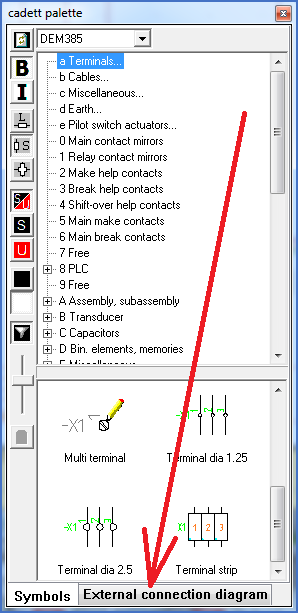
Figure 1474: Click here to start KABGRAF II!
3.The first thing to do is to select which KABGRAF configuration to use.
It is possible for you to have any number of KABGRAF configurations. The configurations control how the External Connection Diagram will look like.
The details about the configurations and which possibilities they give are described in a separate section further down. Please refer to the topic named Configuration.
The selection of KABGRAF configuration is made in the upper part of the window using a so-called ”drop-down list”. Please refer to the figure below.
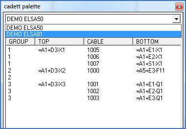
Figure 1475: Selection of KABGRAF configuration
4.Collect the data that are needed for the generation of the External Connection Diagram using the Collect button, as shown in the figure below).
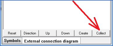
Figure 1476: Click here to collect the data that are needed!
5.All cables are presented as shown in the figure below.
It is then possible for you to manually manipulate the information before the generation itself is made. The manipulations that you are able to do are described in a separate section further down. Please refer to the topic named Manipulation of cable data before generation.
When you are finished with the manipulations, it is time to perform the generation.
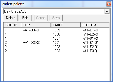
Figure 1477: The cables are presented after a collect has been made.
6.The final step is to start the generation. You do that using the Create button. Please refer to the figure below.
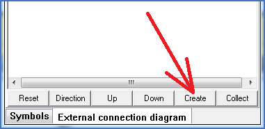
Figure 1478: Generate the External Connection Diagram using this button.
7.The current sheet is left in order to create the new Connection Diagram sheets. For that reason you will have to answer a question of whether the current sheet should be saved or not.
In most cases you will answer with Yes.

Figure 1479: Save current sheet.
8.The External Connection Diagram is created. Dependent on the size of the project and its content of terminals and cables it can contain anything from one single sheet up to a very large number of sheets.
An example is shown in the figure below.
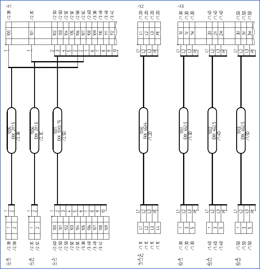
Figure 1480: Example of a generated External Connection Diagram