|
<< Click to Display Table of Contents >> Example of potential references |
  
|
|
<< Click to Display Table of Contents >> Example of potential references |
  
|
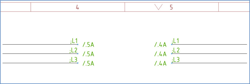
Figure 864: The result of the exercise will look something like this.
The figure above shows three pairs of potential reference symbols, which connect two lines with one another, despite the fact that those lines do not have direct contact. In most cases that would be because they are placed on different sheets, but in this example they are on the same sheet, which will also work fine.
The lines that the potential reference symbols are supposed to be placed upon must be present first, before you can use the Potential reference command. That command is found in the Cables resource category in the Symbol Insert Tool, as shown in the figure below.
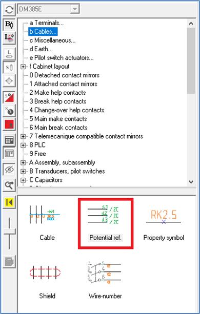
Figure 865: The "Potential reference" command
When you have activated the command, preferably by double-clicking it, you select the first line by left-clicking "before" it. Thereafter, you select the last line by left-clicking "after" it.
•If the lines are horizontal, you first click above the top line and then below the bottom line.
•If the lines are vertical, you first click to the left of the leftmost line and then to the right of the rightmost line.
You will then be asked whether the potential reference text should be rotated 90 degrees or not. The most common answer to that is No, which is also default. The result will then comply with the IEC standard. The other option will not.
Next, you will be asked for an Interval, which is another word for a step value. In most cases you will go for the default, which is 1. (The Interval is a possible step value to increment the potential reference name).
A dialogue box called OnLine Potential reference Dialogue will appear, as shown in the figure below.
You specify a suitable potential name in the Potential name field, for instance ;L1. Press <RETURN>.
The complete potential name is shown in the lower part of the dialogue box.
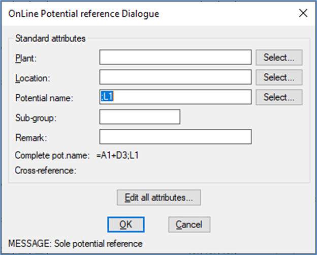
Figure 866: The OnLine Potential reference Dialogue box
If you use project parameters according to the IEC1355 Simplified English prototype project, the composition of potential reference names is:
=Function_(plant) +Location ;Potential_name
;L1 can therefore be interpreted as for example =A1+D3-L1 as shown in the figure above.
There are two other attribute fields available in the dialogue. They are called Sub-group and Remark, and they are associated with separate attributes, one for each. The Sub-group is discussed in a separate sub-topic named exactly that - Sub-group.
Click OK.
The first potential reference symbol will be updated with the attribute values that you have specified, the next potential reference symbol will be inserted, and a corresponding dialogue box will be displayed.
The initial potential name of ;L1 will there be incremented to ;L2.
Click OK once again.
A third dialogue box will appear with ;L3 as default potential name.
A warning will be issued for each potential reference, namely Sole potential reference. That is natural and inevitable, since this is the first potential reference with this name.
Click OK.
The time has come for the other end. Therefore, select the first line of that by clicking above it. Thereafter, select the last line by clicking below it.
Answer No once again to the question about rotating the text 90 degrees.
Confirm the default Interval of 1.
Again, the OnLine Potential reference Dialogue will appear. Instead of entering the potential name manually as before, you may use the Select… button to the right of the Potential name field.
Another dialogue box called OnLine Potential-, Feeder- and Signal designations will then appear, as shown in the figure below.
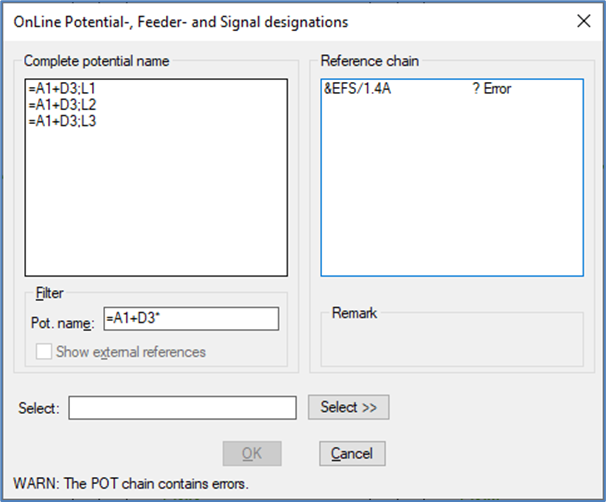
Figure 867: This dialogue is used to select potential name.
In the left part of the dialogue box, you select the ;L1 potential name by clicking it with the left mouse button. Then confirm with the OK button.
You then return to the OnLine Potential reference Dialogue. In the lower part of the dialogue box, you can then see that you have created a chain reference, as shown in the figure below.
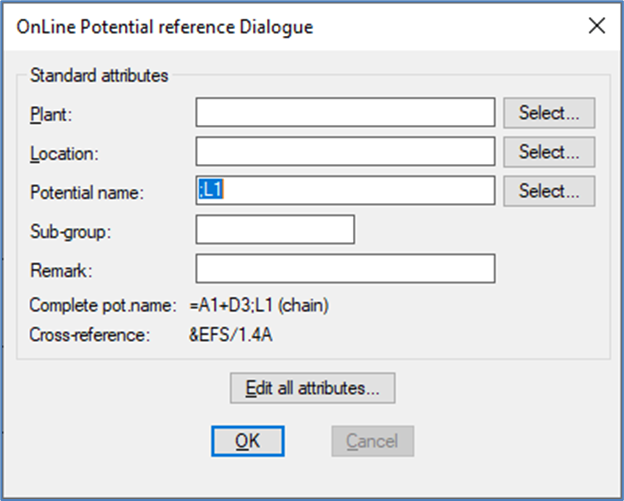
Figure 868: Chain reference
Confirm with the OK button.
Please note that cross-references are created automatically and OnLine.
Click the OK button in the same way in the dialogue boxes for ;L2 and ;L3.
The potential reference macro automatically repeats. Therefore, it asks for a first line once again, when the last potential reference has been conformed.
In that situation, you exit the potential reference command by pressing <RETURN>.
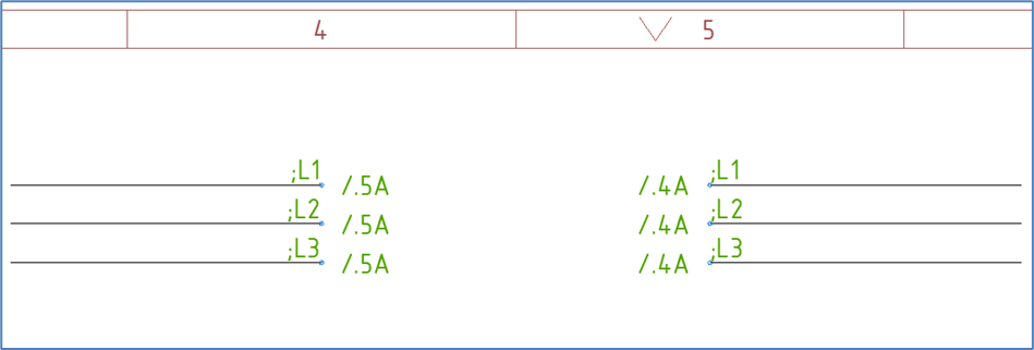
Figure 869: Cross-references have been created automatically and OnLine.
When you move potential references or make other common editing in the circuit diagram sheets, the cross-references will be updated automatically and OnLine.
Connection-wise the effect of potential references is that the lines that are connected are located within the same electrical potential and that the signal name (or potential name) is the same as the potential reference name.
How wiring is calculated is a different topic which is discussed elsewhere, for example in the topic that covers the Wire-list Editor, more specifically in a sub-topic named Background.