|
<< Click to Display Table of Contents >> Background to potential references |
  
|
|
<< Click to Display Table of Contents >> Background to potential references |
  
|
Potential references are used to connect lines between drawing sheets. Two lines that are connected to one another using potential reference symbols, act as if they were the same line, from an electrical interpretation point of view.
A potential reference symbol is always placed in the end of a line. The potential reference is referring to another potential reference, normally placed in another sheet. The connection between the two symbols is established with a common potential name. The potential name can also be considered as a signal name. Potential references will be updated automatically with cross-references by the OnLine Engine.
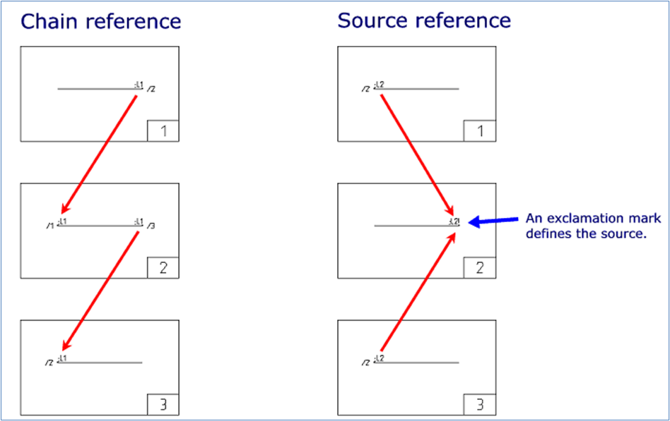
Cross-references between potential references can be arranged in two different ways. They are called “chain references” and “source references” respectively. The figure below explains the difference between the two.

Figure 863: So-called chain references and source references.
Chain references refer to each other two by two in a chain. If you use that variant, it is important that the first sheet in the chain of references have an odd number of references within each potential name. On the last sheet in the chain, there should also be an odd number of references. On all other sheets in the chain, there should be an even number of potential reference symbols.
Why must it be that way?
Otherwise, it would not be possible to match the references two by two in a correct way. Somewhere in the chain, sole references would have to occur. If that happens, cadett ELSA will give priority to references between sheets before references within sheets.
If you for instance have three potential references called L1 on a sheet in the middle of a chain reference, the first L1 will refer backwards to earlier sheets and the last L1 will refer forward to the next sheet where a corresponding potential reference exists. The middle L1 will however generate a warning, namely Sole potential reference.
Source references are simpler. One, and only one, potential reference with a given potential name, is defined as source. All other potential references that share the same potential name, refer to the source. A potential reference is defined as source with an exclamation mark (“!”) in the end of the potential name.
Potential names themselves are regulated by the IEC455 and IEC1175 standards. The handling of them is analogue with the handling of item designations.
IEC445 gives guidelines of how potentials should be named. A few items from IEC445 are listed below.
•The phases in a three-phase system shall be notated L1, L2 and L3.
•The neutral potential shall be notated N.
•In a system of direct current (DC) the poles shall be notated L+ and L- and M for the middle potential.
•An earth potential shall be notated E.
•A protective earth potential shall be notated PE.
•A noiseless earth potential shall be notated TE.
•An earth potential connected to the chassis which is not regarded as a protective earth shall be notated MM.
IEC1175 defines how potential names can be completed with designations for function (plant) or location, which indicates in what equipment the circuit is included. This might result in a potential name, for instance like the following:
=A1;L1
The separator characters for function (plant) and location are the same for potential names as for item designations, which means equal sign (“=”) for function (plant) and plus sign (“+”) for location.
IEC1175 specifies that the separator character between function (plant) and/or location, and the rest of the potential name must be a semicolon (“;”). If you specify ;L1 as potential name, function (plant) and/or location will be retrieved from the drawing frame (upper left corner in most cases) or from a surrounding boundary box according to the composition of potential names in the project parameters.