|
<< Click to Display Table of Contents >> Connected symbols |
  
|
|
<< Click to Display Table of Contents >> Connected symbols |
  
|
The Connected symbols command is found directly above Connection view in the ribbon menu.

Figure 1374: The "Connected symbols" command
Like Connection view, Connected symbols is a powerful tool to check connections, but it is more selective and goes in more detail. With the Connected symbols command, you check one electrical node at a time. It does not matter whether the node in its entirety is found in a single drawing sheet or if it is spread over many.
You use this feature in the following way:
Select the Connected symbols command. You are asked whether you want to check a whole node or only a sub-node.
•A node is almost the same as an electrical potential. Conventional symbols are regarded as breaks while terminals and connectors are regarded as connections, which means that you have the same node on both sides of a terminal. On the respective sides of for example a fuse, you have however different nodes. The other side of a break contact is in the same way regarded as another node. The reason is that a break contact of course can be open.
•For a sub-node, on the other hand, terminals and connectors are regarded as breaks.
Select Node with the letter N or Sub-node with the letter S. Sub-node is default, which means that if you simply press <RETURN>, the result will be Sub-node.
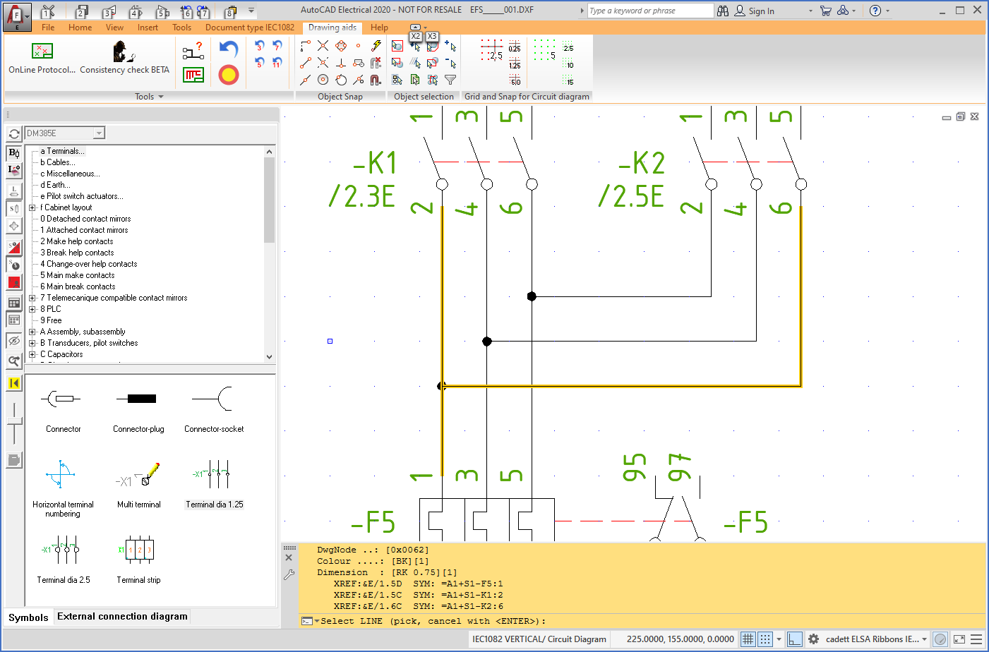
After specifying type of node, you select a line somewhere in the circuit diagram. All lines within the node or sub-node that you have selected in this way will be displayed in yellow colour on the screen.
Please refer to the figure below, which shows how that will look.

Figure 1375: A selected node is displayed with yellow colour.
All connection points within the selected node or sub-node are listed in plain language on the command line, with one connection point per line. The number of connection points might be too great to fit the command line. If so, you can use the <F2> key to invoke the AutoCAD text window. In principle, that makes it possible to view an unlimited number of lines, meaning to receive complete information about the entire node or sub-node. The <F2> key “toggles”, meaning that every second time you press it, the text window is displayed, or hidden.
Using this command, you get a proper verification that cadett ELSA is interpreting the selected part of the circuit diagram in the way that you intend. In cases where it is not, when the result is not what you expected, the reason may be a genuine drawing error, or that the content of the OnLine database does not correctly reflect the circuit diagram. If you suspect a “ghost error”, meaning that the circuit diagram looks correct but the information you get from the Connected symbols command indicates an error, you should regenerate the OnLine database and thereafter select the Connected symbols command again. If the error remains, the error is real, and must be fixed in the circuit diagram.