|
<< Click to Display Table of Contents >> Connection View |
  
|
|
<< Click to Display Table of Contents >> Connection View |
  
|
The Connection view command is found in the Tools panel, as shown in the figure below.

Figure 1503: The "Connection view" command
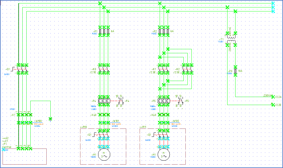
All lines in the current drawing sheet that constitute connections, will be displayed in green colour when you select the Connection view command. This is a quick and very effective way of verifying that what you have drawn has been interpreted in the intended way by the software. Lines that hit connection points of symbols in a correct way are displayed with green crosses. Connection points that are not hit by any lines are displayed with light blue (cyan) crosses. Endpoints of lines that neither hit a symbol, nor another line, are also displayed with light blue crosses.

Figure 1504: The “Connection view”
Cable cores and Donuts are also shown with green crosses when they are placed correctly.
When you get used to it, the Connection view will help you to discover any connection errors in a circuit diagram in a matter of a few seconds. It is a good and extremely profitable habit, to check the Connection view for each new sheet that you create or edit. Those few seconds will become one of your best investments.