|
<< Click to Display Table of Contents >> Basic information about generic symbols |
  
|
|
<< Click to Display Table of Contents >> Basic information about generic symbols |
  
|

Figure 917: xxx
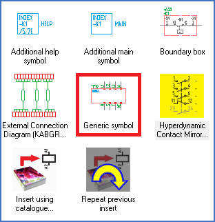
The Generic Symbol is a so-called “black box”, a “quick symbol”, which is a box of arbitrary size with arbitrary connections that can be used to symbolise any kind of device.
The Generic Symbol is extremely practical and very useful in many situations.
The Generic Symbol is fully supported by the OnLine Engine, which essentially treats it in the same way as other symbols, for example when generation of device lists and wire-lists are concerned.

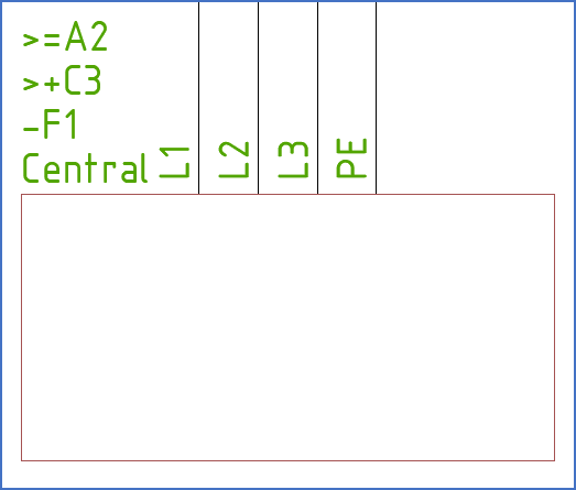
Figure 918: A “Generic Symbol” in a final documentation (with a PLOT layer setting)
The Generic symbol can for example symbolise a circuit board, a fuse central or some other larger unit that you buy as a unit and connect as a unit, but which itself consists of multiple parts. The reader of the circuit diagram is maybe interested in knowing what function that unit has. The electrician who is connecting it, is however probably most interested in how to connect the entire unit.
The connection generation must then stop at the connections to the Generic symbol. You may draw symbols inside the Generic symbol to explain its function. These symbols are meant as information to the reader of the circuit diagram, but nothing else. They should not be included in device lists or wire lists. This is accomplished by drawing everything inside the Generic symbol in a non-electric layer. Like the DEKOR35, which is shown in red colour.