|
<< Click to Display Table of Contents >> Colour |
  
|
|
<< Click to Display Table of Contents >> Colour |
  
|

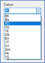
Figure 496: Selecting a new default colour
The Colour project parameter specifies the default colour for wires. This means that the colour that you specify here, will be used for all wires for which no other colour specification is available. Such other specifications can be made in the circuit diagrams either in property symbols or in wire number symbols.
Colours that you define in the wire list of Dynamic OnLine I, will be transferred to the wire number symbols automatically.
You specify the default colour by selection in the drop-down list that is available for the purpose, and which you access using the arrow-button to the right of the Colour field.
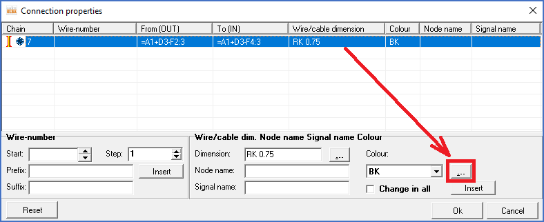
If you want to add colours to the list, you do that from the Wire list of the Dynamic OnLine I, where you right-click and select Edit connection properties. In the dialogue box that is then displayed, you will find a button labelled with three dots to the right of the colour that is presented in the dialogue. If you click that button, you will enter an editor for available colours. Please refer to the Editing the list of selectable colours sub-topic of the Dynamic OnLine I main topic.

Figure 497: The "Connection properties" dialogue of the "Dynamic OnLine I Wire list"
Technical note
The colours that are available to select between are defined in a database file called COLORS.DBF, which is located in the \ELSA\SYSTEM directory.