|
<< Click to Display Table of Contents >> “Open” the symbol for editing |
  
|
|
<< Click to Display Table of Contents >> “Open” the symbol for editing |
  
|
“Open” the symbol for editing using the Symbol generator: 3. Edit command, which is found in the Symbols panel of the Home tab in the ribbon menu, as shown in the figure below.
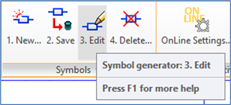
Figure 950: The "Symbol Generator: 3. Edit" command
You will be asked to select an object. Pick the symbol!
Something that looks like an “extended explode” will take place. The Symbol Generator Objects that were described above will be visible along the graphical objects and the attribute definitions of the symbol itself, like shown in the figure below.
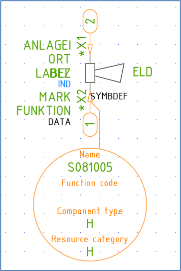
Figure 951: The horn after it has been “opened” for editing
▪In the Symbol Object, which looks like a big balloon with an arrow, the name of the symbol, the component type letter code, and the resource category are shown.
▪The Connection Objects look like small balloons with arrows pointing at the connection points. In each balloon, a number is shown that indicates the order among the connection points.
For several reasons, among them readability, it is possible to rotate the graphical Symbol Generator Objects. To do so, you use the ROTATE command. Please note, that you will not need to define any base point. You can start the rotation immediately. The base point is automatically defined as the arrow-head.
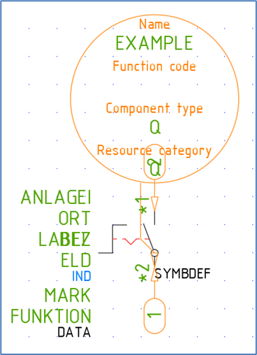
Figure 952: This is an example where the Symbol Object has ended up on top of other objects.
The Symbol Object can be rotated in any direction, but the rotation only affects appearance, not functionality in any way. The only reason for rotating it, is to avoid having “the balloon” on top of something, which may make it difficult to read the text.
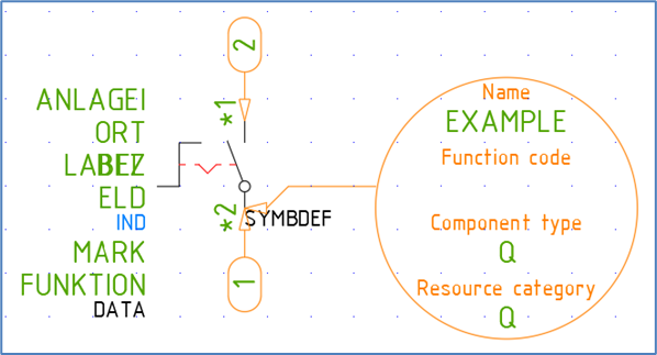
Figure 953: By rotating the Symbol Object using the ROTATE command, it has been made much easier to see all details.
The Connection Objects can be rotated in steps of 90 degrees. That direction is however significant, with an important functionality associated with it, namely that the direction of the Connection Object specifies the direction of the lines that are expected to connect to the symbol. That information is used by the line break function, for which it is essential.
The two figures below show two symbols with two connection points each, where the placement of the connection points relative to one another is identical, but where the directions differ.

Figure 954: One line is supposed to extend to the left, the other to the right.
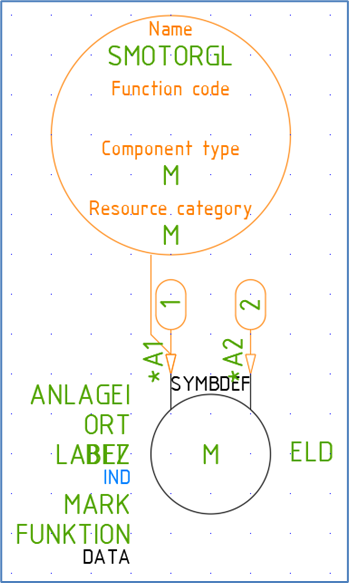
Figure 955: Both lines are supposed to extend upwards.
Besides the graphical Symbol Generator Objects mentioned here, the symbol will be exploded in the conventional way, which means that the attributes will be movable and editable, and the graphics will consist of single AutoCAD objects.