|
<< Click to Display Table of Contents >> Example of legacy project related drawing types |
  
|
|
<< Click to Display Table of Contents >> Example of legacy project related drawing types |
  
|
An example of the use of project related drawing types is found in the German DIN demonstration project, which is simply named Demonstration project, short project name 0DMDIN, located in the DIN sub-group of the Samples group).

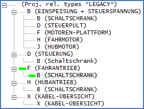
Figure 614: When creating new sheets, the following legacy project related drawing types is displayed in the DIN Demonstration project.

Figure 615: When editing document codes in the DIN Demonstration project, the definitions are all visible.
The first project related drawing type is used to specify plant, while the second project related drawing type is used for location. The second project related drawing type is considered to be a sub-level of the first. This example is therefore useful primarily for item designations used in an old IEC750-like way, where location is regarded as a sub-level of plant in a corresponding way.
The DIN example is described in more detail by the table below, where the German descriptions have also been translated to English.
Proj. related drawing types |
Document code |
Short descriptions |
Description |
||
|---|---|---|---|---|---|
First |
Second |
First |
Second |
||
B |
B_ |
=1A10 |
Feed and control voltage |
||
B |
BB |
+3E01 |
Switch cabinet |
||
D |
BD |
+3P01 |
Control panel |
||
F |
BF |
+1T01 |
Motor platform |
||
H |
BH |
+1T10 |
Drive motor |
||
J |
BJ |
+1T20 |
Lift motor |
||
D |
D_ |
=1A20 |
Control |
||
B |
DB |
+3E01 |
Switch cabinet |
||
F |
F_ |
=1D10 |
Traction drive |
||
B |
FB |
+3E01 |
Switch cabinet |
||
H |
H_ |
=1D20 |
Lifting drive |
||
B |
HB |
+3E01 |
Switch cabinet |
||
X |
X_ |
=W00 |
Cable overview |
||
X |
XX |
Cable overview |
|||
The main idea behind a configuration like this one, is to allow for a plant and location dependent sheet numbering, with file names that have both plant and location encoded in them. Structures like that are highly recommended for large projects or super projects, where multiple engineers are working with different parts of a large design simultaneously.
More up to date variants of this way of organising a project, with extended functionality like support for multiple levels, are of course also available. One example of that is discussed in the Example of user defined document codes sub-topic.