|
<< Click to Display Table of Contents >> Conventional contact mirror |
  
|
|
<< Click to Display Table of Contents >> Conventional contact mirror |
  
|
In most cases, creating a conventional contact mirror symbol is best done from scratch.
When inserting the needed function objects (contacts), you can automatically get suitable graphics compatible with the standard contact mirrors of cadett ELSA.
If you for one reason or the other want your contact mirrors to look differently, you can of course make them so, but in that case you need to draw the graphics of the contacts yourself.
The descriptions below, assumes that you use standard graphics, and are detailed step-by-step explanations hos to make up your contact mirror in the most effective way
First, you should create a plan, meaning that you decide exactly which type of contacts to include, in which order, and with which connection point numbers.

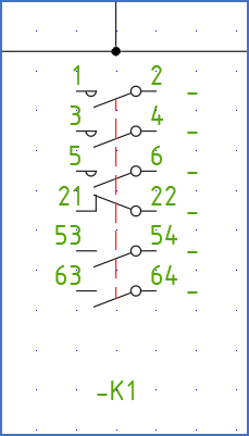
Figure 1106: This is where we are heading.
Example:
- A three phase make main contact with connection point numbers 1, 2, 3, 4, 5, 6.
- Thereafter, a break help contact with connection point numbers 21, 22.
- After that, two make help contacts with connection point numbers 53, 54 and 63, 64 respectively.
The first three phase main contact will be implemented with three make main contacts.
Next, you must decide if your contact mirror should be for vertical or horizontal circuit diagrams.
Two separate sub-topics are available. The first one describes in full detail hos to create a vertical contact mirror. The second one focuses on what is different when creating a horizontal.
•Detailed example of a vertical contact mirror
•The differences for a horizontal contact mirror