|
<< Click to Display Table of Contents >> Connection data dialogue |
  
|
|
<< Click to Display Table of Contents >> Connection data dialogue |
  
|
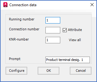
When you click the Connect.>> button, a Connection data dialogue box like shown in the figure below, will be displayed.

Figure 994: The "Connection data" dialogue box
In that dialogue box, you enter a suitable default connection point number of the new connection point, and you specify whether the connection point number should be editable or not, or in other words if it should be stored in an attribute or not.
After that, you click OK and you will insert the connection point object, by first placing the insertion point in the exact place where the connection point should be, and then select a proper direction by pointing in the direction of a future line from the connection point in question.
When that is done, and the connection point object is in its place, you will return to the Connection data dialogue box, where you can define the next connection point.
You continue that way, until you have defined all connection points that you want to have, at which time you click Cancel in the Connection data dialogue. You then return to the main dialogue, the one named Symbol data.
The details of the Connection data dialogue are described in the sub-topics that are listed below.