|
<< Click to Display Table of Contents >> Configure button |
  
|
|
<< Click to Display Table of Contents >> Configure button |
  
|

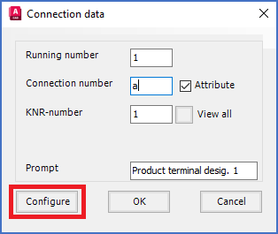
Figure 1009: The "Configure" button with which you can extend the "Connection data" dialogue
The position and other attribute properties of the connection point number attribute (KNR) has four separate sets of default values, for the four possible directions of a connection point (left, up, down, right).
Directions in AutoCAD are by default defined as 0 to the right, and positive angles counter-clockwise. Please refer to the table below.
Direction |
Angle |
|---|---|
Right |
0 |
Up |
90 |
Left |
180 |
Down |
270 |
The Configure button in the Connection data dialogue box, makes it possible to deviate from the default properties for individual connection point numbers. Please note that any changes that you do in that way, will affect the current connection point only.
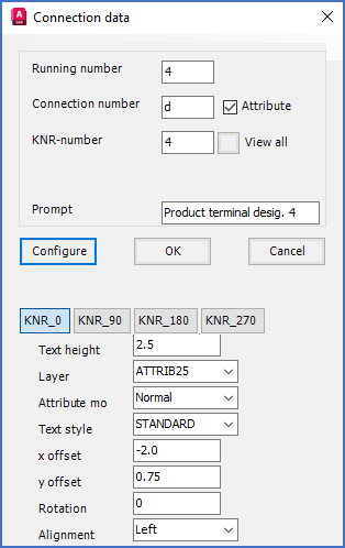
If you click the Configure button, the Connection data dialogue box will be extended with a number of additional fields, as shown in the figure below.

Figure 1010: The extended variant of the "Connection data" dialogue
You are then able to adjust details when the connection point number attribute is concerned, as text height, layer, attribute mode, text style, x and y position relative to the position of the connection point, rotation and text justification.