|
<< Click to Display Table of Contents >> Symbol Generator Objects |
  
|
|
<< Click to Display Table of Contents >> Symbol Generator Objects |
  
|
To offer a good usability and interactivity in the creation and management of symbols, all information is displayed graphically on the screen. To accomplish this, the Symbol Generator uses graphical objects showing the information that is stored in the symbol database.

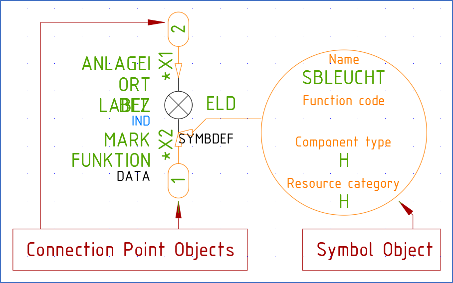
Figure 772: This is a conventional main symbol when edited with the Symbol Generator. Please note the Connection Points Objects that define connection points, and also the Symbol Object that defines the name of the symbol, the insertion point and more.

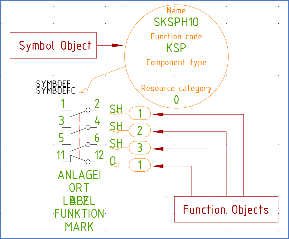
Figure 773: This is a contact mirror that is edited with the Symbol Generator. Please note the Function objects and the Symbol Object.
These “Symbol Generator Objects” are of three kinds, described in the table below, and shown in the two figures above.
Symbol Generator Object |
Description |
|---|---|
Symbol Object |
There is one Symbol Object for each symbol. This object shows the name of the symbol, the component type letter code, the resource type and so on.
Besides that, it shows where the insertion point is situated.
|
Connection Object |
For each connection point, there is one Connection Object. The Connection Object shows where the connection point is located, and what connection number or attribute for the connection number that is associated with the connection point.
Besides that, the direction of the connection point is shown, meaning in what direction lines connected to the connection point are expected to go. That information is used by the line break feature.
|
Function Object |
The Function Object is used for mirror symbols, like contact mirrors and PLC mirrors. There is one Function Object for each function in a mirror symbol. In other words, there is one Function Object for each contact in a contact mirror, and for each input or output in a PLC mirror.
|
The reason for storing important information in this way, in a separate symbol database instead of in the symbol itself, is that the OnLine Engine can reach the information much faster and efficiently that way. It simply gives superior performance. On the other hand, it could result in poorer security since the system in this way depends on the symbol database. That disadvantage is however eliminated by a backup of the database information being stored in the symbol. If the information in the symbol database is lost, it can be recreated directly from the symbol.