|
<< Click to Display Table of Contents >> Graphical adjustments |
  
|
|
<< Click to Display Table of Contents >> Graphical adjustments |
  
|
At this stage, you can make the changes you need to get the symbol to look like you wish. Start with the graphical adjustments. For that purpose, you can use all ordinary commands in AutoCAD.

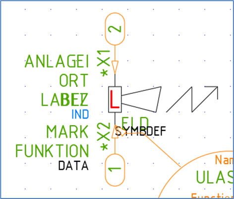
Figure 930: The horn has been graphically adjusted to become a laser siren.
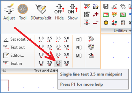
In the example with the laser siren, you will have to draw the flash at the horn with ordinary lines. The electrical data attribute must be moved to another place, for instance by using the Move command. Otherwise, it will interfere with the flash. You draw the letter “L” in the middle of the box, either with lines or with text, for instance a 3.5 mm single line text with justification Midpoint, as shown in the figure below.

Figure 931: Single line text in the “Text and Attributes” panel