|
<< Click to Display Table of Contents >> Connection points |
  
|
|
<< Click to Display Table of Contents >> Connection points |
  
|
When you created a symbol from an existing one, the connection points were already defined, and you did not have to worry about them. That is in fact a major advantage of that method. When creating a symbol from scratch, you naturally must define the connection points one by one.
To do so, click the Connect.>> button.
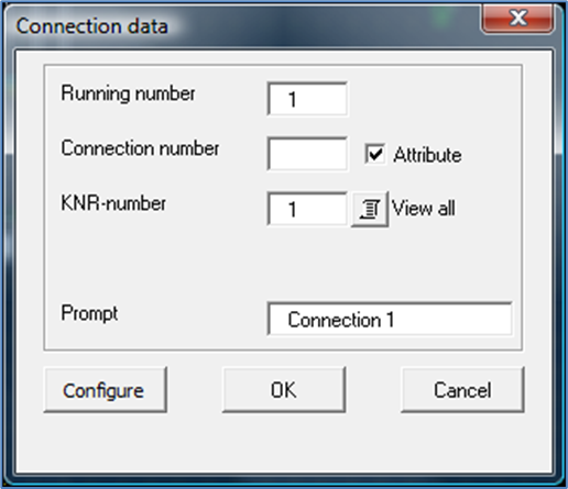
A special connection point dialogue box will appear, as shown in the figure below.

Figure 941: Dialogue box for connection points
The Running number specifies which connection, in a sequence of many, the current dialogue deals with. It is of limited significance and should mainly be regarded as an information of where you are in the process.
The designation of the connection, the Connection number, can be either fixed or editable. An editable connection number is stored in an attribute, and can therefore be changed anytime, without changing the symbol itself. A fixed connection number is stored in the symbol itself and cannot be changed without changing the symbol definition. Such a fixed connection number is stored in the symbol database only. If you want to display it, you can do that with a fixed text in the symbol. For editable connection numbers, the connection number specified in the dialogue, is the default.
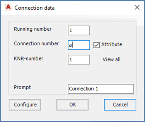
Editable connection numbers, in attributes, are in most cases the better option. Therefore, please check Attribute. Then, enter a suitable default Connection number for the first connection, for instance a.

Figure 942: Specify default connection number, and whether it should be editable or not.
The KNR number specifies the attribute name for the Connection number. Attribute names for connection numbers will be KNR1, KNR2, KNR3 and so on.
When you have specified all the above, you must specify where the connection point should be placed. Click the OK button to do so.
Then click in the position of the connection point. In most cases it is best to place it in the end of a line that starts from the symbol, in the very same way as in most standard symbols. This will make it clear where the connection point is located, and at the same time leave room for the connection number.
After specifying where the connection point is, will also have to specify which direction it should have. You do that by pointing in the direction that a line from the connection point in question will have. This information is important for the line break feature as well as for how to place and rotate the connection number.
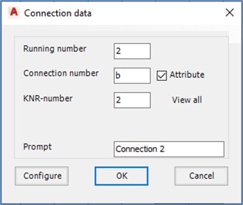
The first connection point is then completely defined, and the dialogue box will appear once again giving you the opportunity to specify the next connection point.

Figure 943: The second connection can have "b" as default.
This procedure will be repeated, over and over again, so that you can define any number of connection points.
The default for the second connection number can be set to b.

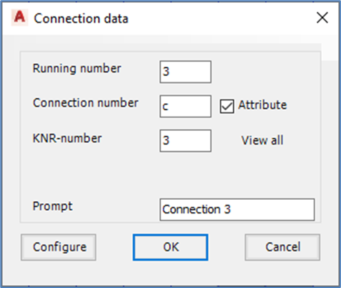
Figure 944: A third connection point will not exist for this symbol. Therefore, click "Cancel".
The laser siren in the example only has two connection points. Therefore, when the dialogue for the third connection point appears, click the Cancel button appears.