|
<< Click to Display Table of Contents >> Changing node name and signal name |
  
|
|
<< Click to Display Table of Contents >> Changing node name and signal name |
  
|
In a similar manner described in the previous sub-topic for dimensions, you can change node names and signal names.
You can specify node names and signal names in one way only, namely to type it in the fields that are available for the purpose.
When you click the Insert button in the Wire/cable dim. Node name Signal name Colour section, all the properties that you have entered there are transferred to the wires that you have selected, or to all wires in the dialogue box if you have selected the Change in all option.
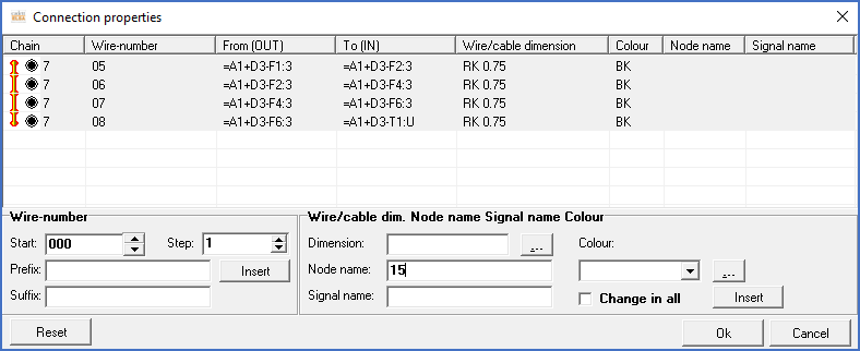
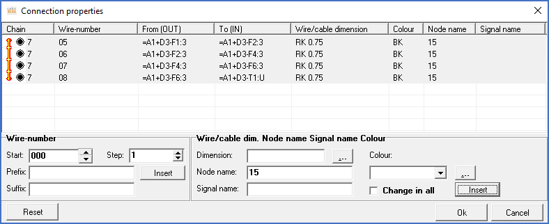
The figures below, shows an example where four wires are given a node name (15).

Figure 1561: Four wires have been selected and a new node name ("15") has been typed in the "Node name" field.

Figure 1562: After pressing the "Insert" button, the specified node name is visible for all four wires in the dialogue box.

Figure 1563: After clicking the "Ok" button in the dialogue box, the specified node name has been trasferred to the main wire list. The changes are marked with ticks to the left. To transfer the changes to the circuit diagrams, you click the "Insert" button.