|
<< Click to Display Table of Contents >> Property symbol |
  
|
|
<< Click to Display Table of Contents >> Property symbol |
  
|

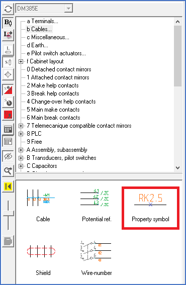
Figure 871: The “Property symbol” command
The Property symbol offers an elegant and convenient opportunity to specify wire properties directly in the circuit diagram. The properties in question are for instance Dimension, Colour, Signal name, or Node name.
You insert the property symbol from the Symbol Insert Tool, section b – Cables, and finally Property Symbol, as shown in the figure above.
You pick the lines that represent the wires, sub-nodes, or nodes that you want to specify properties for. You pick the lines in the same way as for terminals and other symbol macros. First before the first, then after the last.
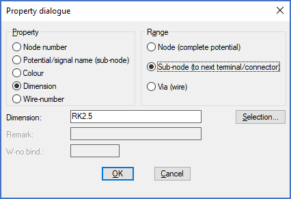
A dialogue box will then appear in which you first select which property you wish to specify. That dialogue box is called Property dialogue, and it is shown in the figure below.

Figure 872: The "Property" dialogue
There are five different properties to select from. They are:
▪Node number is the name of the entire electrical potential. The common term for an entire electrical potential in cadett ELSA is a “node”. This property is used for so-called “node numbering”, as opposed to “wire-numbering”. The range of this property is always a node.
▪Potential/signal name (sub-node) corresponds to potential name in the potential reference symbols. Often this is a signal name (like START) or a potential name like L1, 24V or similar. The range of this property is always a sub-node, so it could also be called a “sub-node name” or “sub-node number”.
▪Colour is a well-known term. Some common examples are black, red, blue, and green. The colour of course refers to the colours of physical wires. Usually, the colour is indicated by an abbreviation such as BK for black, or RD for red.
▪Dimension refers to the type of wire that is in use, for instance RK1.5, RK2.5 and so on.
▪Finally Wire-number is the designation of a single wire.
When you have selected which property you wish to specify, you also must select the range of that property. The property might comprehend the Node (complete potential), the Sub-node (to next terminal/connector) or a Via (wire) which is a single wire.
▪A dimension of RK2.5 might for instance be valid for all wires within the node in which you have inserted the property symbol. In that case, in the Range section, please check Node (complete potential).
▪Another possibility is that the specified dimension is valid for the current sub-node only. In that case, please check Sub-node (to next terminal/connector. When determining where a “sub-node” ends, terminals and connectors are considered as breaks. The term “to next terminal/connector” comes from there.
▪The last possibility is that the dimension only will be used for a via, one single wire. In that case, please check Via (wire). For this alternative you should note that it is useful only if you have inserted the property symbol so that it unambiguously refers to a single wire. That might be the case only for pure point-to-point connections with no diversions, or if you are using forced connections (where the wiring order is specified with lines in 45 degrees angles).
All properties can for natural reasons not be combined with all different ranges. For instance, a node name always refers to an entire node. Something else would be unthinkable, for obvious reasons.
The same is valid for Potential/signal names, which always refer to a sub-node, never to anything else.
Colours, on the other hand, may have all three possible ranges. The same is valid for dimensions. Wire-numbers, finally, can of course only have the range of a Via (wire), which means a single wire.
If you would like to specify several properties, for instance both colour and dimension, you must insert several property symbols. Each property symbol defines one single property.
The properties that you define in this way, will be used for the wire lists that you create in the project. In the Wire-list Editor, you can see the effects of the property symbols immediately. If you create wire lists using the Report Generator, the property information will of course be part of those lists as well.
Please refer to the Wire-list Editor topic for more information about wire-properties in general.
Technical information
The connection properties colour and dimension can be specified with three different methods in cadett ELSA. In the project parameters you can specify default values for colour and dimension. These values will be used in situations where colour and/or dimension are not specified in any other way, which means with the lowest priority. The property symbol is the second method to specify these properties. The property symbol has higher priority than the default values in the project parameters. The third method to specify dimension or colour is by using the wire-number symbol. These specifications have the highest priority, which means higher priority than the property symbol. If you assign dimension and/or colour via the Wire-list Editor, these specifications will be transferred to the wire-number symbols of the circuit diagram. Unlike the property symbol, properties specified in wire-number symbols can refer to single wires even in circuit diagrams that are drawn without forced connections.