|
<< Click to Display Table of Contents >> Layer selection |
  
|
|
<< Click to Display Table of Contents >> Layer selection |
  
|

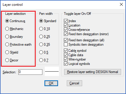
Figure 1515: The "Layer selection" section
In the Layer selection section to the left in the dialogue box, you can select which layer should be active, meaning which layer to draw in.
•Continuous refers to layer 0 (zero), which is the most important electrical layer, and which has white colour. It is there you normally should draw your lines and insert your symbols. Please note that “white” is displayed as black on a white background.
•The Mechanic layer is used for mechanical links. To select this layer manually is very rare.
•Boundary refers to the BOUNDARY layer, where the boundary boxes are placed. To select this layer manually is also very rare.
•Protective earth refers to the PE layer, which has white colour and a dashed line-type. The PE layer is electrical.
•Shield refers to the SHIELD layer, which is non-electric, has red colour and dashed line-type. Shield symbols are placed there. This layer as well is rarely used manually.
•Décor refers to a line of decorative non-electrical layers. The décor layers are used to draw things that the cadett ELSA OnLine Engine should ignore. The names of the décor layers are DEKOR18, DEKOR25, DEKOR35, DEKOR50, and DEKOR70, where the digits refer to line thicknesses. DEKOR35 for example is normally printed with a line thickness of 0.35 mm on an A3 paper, corresponding to 0.25 mm when reduced 29 % in size to print on an A4 paper. The choice of which décor layer to use is controlled by selection of Pen width made in the Pen width section of the dialogue box.