|
<< Click to Display Table of Contents >> Layer management in cadett ELSA |
  
|
|
<< Click to Display Table of Contents >> Layer management in cadett ELSA |
  
|
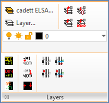
Layer management commands in cadett ELSA are collected in the Layers panel of the Home tab in the ribbon menu.

Figure 967: The “Layers” panel of the “Home” tab
In cadett ELSA, precisely as when using plain AutoCAD, you can use as many layers as you want, and they can have any names that you want. However, a few predefined layer sets are included in the delivery of cadett ELSA, one for each symbol library. These standard layer sets each contain around 50 – 120 layers each, and they are all well suited for common electrical design work. In most cases there is no reason to change these layer sets or to add layers to them, even if it is possible to do that.
In the same way as in plain AutoCAD, every layer has a colour. You are strongly recommended to use object colour Bylayer. In that way you ensure that it is easy to see in which layer an object is located, simply from the colour of the object. It is highly beneficial to be able to do that.
Layers in AutoCAD have a few other properties as well, beside the colour. For example, each layer has a linetype. You can also turn a layer ON or OFF, and you can FREEZE or THAW it.
An additional property is added in cadett ELSA, on top of the ones that standard AutoCAD offers. A layer is here either “electrical” or “non-electrical”.
•An electrical layer is a layer with logical function. The OnLine Engine will automatically try to interpret anything you put into a layer of that kind. Lines in electrical layers will be interpreted as connections. Symbols in electrical layers will be interpreted as devices. Checking and control will be applied on all objects in such layers.
In the IEC symbol libraries, white colour is used to distinguish electrical layers from non-electrical. Please note that “white” is shown as black on a white background.
•Non-electrical layers are “stupid” in the sense that the OnLine Engine of cadett ELSA completely ignores everything in them. No checking or control is applied on objects in such layers.
To easily distinguish non-electrical layers from electrical, non-electrical layers have other colours than white.
Non-electrical layers are useful for several purposes.
Equipment that does not belong to your design, but which nevertheless is essential as an orientation for the understanding, may for example be drawn in non-electrical layers. When doing so, the external equipment will still be visible in the circuit diagrams, but it will not be part of the reports, like device lists, cable lists, and wire lists.
In the Layers panel of the Home tab in the ribbon menu, you find commands for layer management.

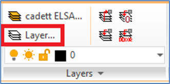
Figure 968: The "Layer" command
Please start by testing the Layer command, which is the standard command for layer management in AutoCAD. That command displays a palette containing a complete list of all layers in the current drawing sheet.
Please note that what is said above about colours, is primarily referring to IEC symbol libraries. In contemporary layer sets of the DIN5 symbol library, different shades of grey are used for electrical layers, depending on the desired line width. Legacy DIN5 layer sets do not distinguish between electrical and non-electrical layers with colours. That is of course a strong argument for not using such layer sets.
Details about layer sets, colours, and background colours are found in the topics listed below.