|
<< Click to Display Table of Contents >> Between two functions |
  
|
|
<< Click to Display Table of Contents >> Between two functions |
  
|
A signal - ;START - goes via a potential reference between two circuit diagram sheets displayed in the figure below.

Figure 609: The two circuit diagram sheets of the example
The document kind is identical - &EFS. However, the function designation differs.
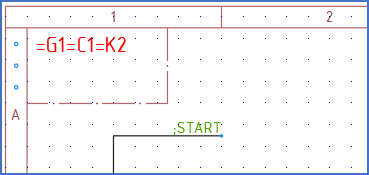
Figure 610: The START signal comes from =G1=C1=K2. A potential reference symbol is inserted and the signal name ;START is specified.
The figure above shows the first potential reference, directly when it has been inserted in sheet 4 of =G1=C1=K2.
Please note that the other end does not exist yet. Therefore, no cross-reference appears.
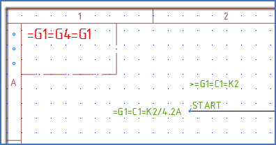
Figure 611: In the second sheet, which has the function designation =G1=G4=G1, a second potential reference symbol is inserted. The first potential reference is selected. Here is the result.
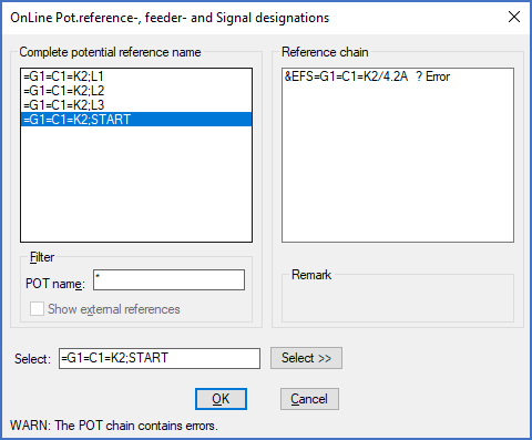
Figure 612: Selection of potential reference name
The figure above shows the other end in sheet 1 of =G1=G4=G1. A potential reference symbol has been inserted and the signal name has been selected using the Select button the potential reference dialogue box.
Since the other end is located in another part of the plant, the signal name ;START is ambiguous and need to be completed with the complete function designation. That is added automatically when selecting the signal name as shown in the figure above.
The cross-reference that is created instantly and automatically, does not contain a DCC code, but it does contain a function designation. The reference is within the same DCC code but to another function/plant. Therefore, the DCC code has been removed by the redundancy reduction feature, while the function still remains. In that way, the cross-reference is unambiguous, while it is kept as short as possible.
The function specification above the potential reference symbol might be somewhat confusing and also not practical if multiple lines with a distance of 5 mm have potential reference symbols. There is simply no room for that information. However, a nice solution to that problem is available and shown in the figure below.
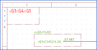
Figure 613: A boundary box, like this, makes the situation somewhat easier for the reader of documentation to understand.
A boundary box is added surrounding the potential reference symbol. The boundary box is used to specify the function of the other end. An automatic redundancy reduction of the function designation is then performed, as soon as you double-click the potential reference symbol. That way of presenting a potential reference between different functions or document kinds, is better in many ways. It is easier to interpret and solves the room problem discussed above.
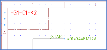
Figure 614: When the second end is correctly defined, the first end will get its cross-reference automatically.
When the second end is correctly defined, the first end, where we started, will be automatically updated with an unambiguous cross-reference, as shown in the figure above.
When double-clicking the potential reference symbol above, the dialogue box that is displayed will look like shown in the figure below.
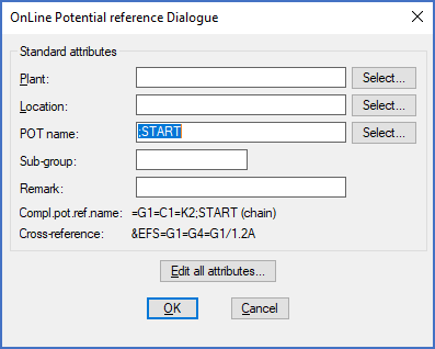
Figure 615: The specified signal name - ;START - is interpreted based on ist context. In this case the complete signal name is =G1=C1=K2;START.
Please note that the complete signal name is =G1=C1=K2;START and the complete cross-reference is &EFS=G1=G4=G1/1.2A. Automatic redundancy reduction has been applied to both.