|
<< Click to Display Table of Contents >> Use of the command |
  
|
|
<< Click to Display Table of Contents >> Use of the command |
  
|
When you have activated the Terminal Direction Editor command, either using the menus or by typing the CAELCHANGETERMINALDIRECTION command, you will be asked to select objects. You can then use ordinary object selection methods, like Window, Crossing and similar, to select the terminals that you want to adjust the direction for. You can select any number of terminals within the current drawing sheet.

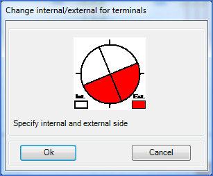
Figure 1435: The Terminal Direction Editor Dialogue box
After you have confirmed your selection with the <RETURN> key, a dialogue box is displayed, where you can easily specify the directions that you would like to have for all selected terminals. Please note that all selected terminals will get the same directions and that the default displayed in the dialogue is always the same, regardless of the current directions of the selected terminals.
You can easily change the directions, by simply left-clicking the circle section that you want to alter.
As always, red symbolises the external side of the physical terminals, and white/black the internal side.
When you confirm the specified directions in the dialogue box using the Ok button, the operation is performed and the terminals will get their new directions. If the current layer setting is correct for design work, you will see the effect immediately.