|
<< Click to Display Table of Contents >> Add objects to an option |
  
|
|
<< Click to Display Table of Contents >> Add objects to an option |
  
|
To add objects to a specific option, you will have to methodically open each sheet where those objects are located and select the objects in question for the option:
1.Open a sheet where such objects are located.

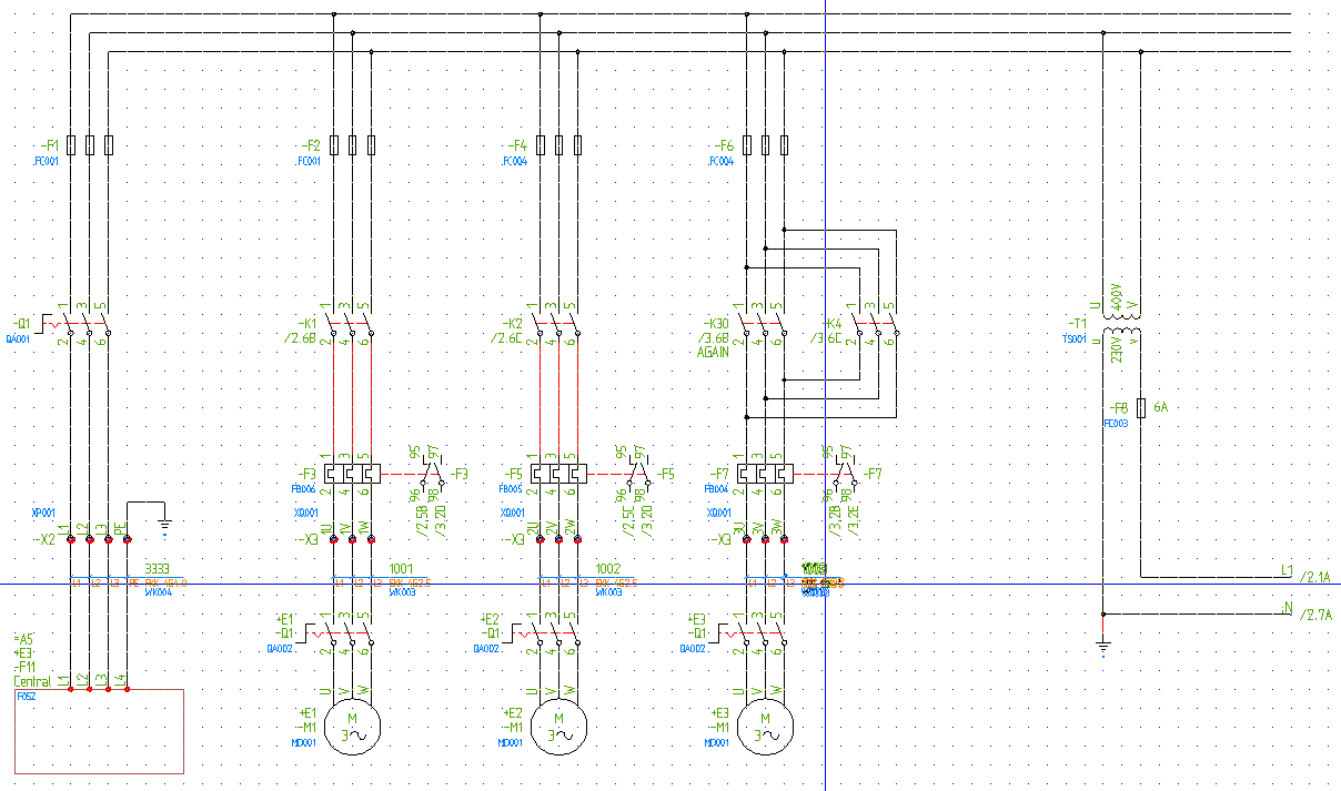
Figure 2270: The first sheet of the “Demonstration project IEC1082” is used in the example discussed here
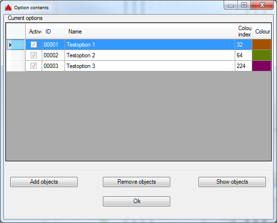
2.Selecting the Add/remove objects command in the menus (or typing CAELOPTIONSOBJECTS), displays the Option contents Dialogue Box, which is shown in the figure below.
3.In the Current options list, select the option that you want to add objects to.

Figure 2271: Selection of an option to add objects to
4.Click the Add objects button.
5.Select the objects that should belong to the selected option. Confirm the object selection with the <RETURN> key in the ordinary manner.
6.This brings you back to the Option contents Dialogue Box, and the result is visible immediately, even before you exit the dialogue box with the Ok button.
Please note that you can continue to add objects to other options as well, without exiting the Option contents Dialogue Box.

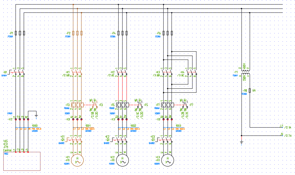
Figure 2272: The first motor circuit has been made part of an option.
In the picture above, all objects belonging to the first of three motor circuits have been made part of “Testoption 1”. The colour of this option is number 32.
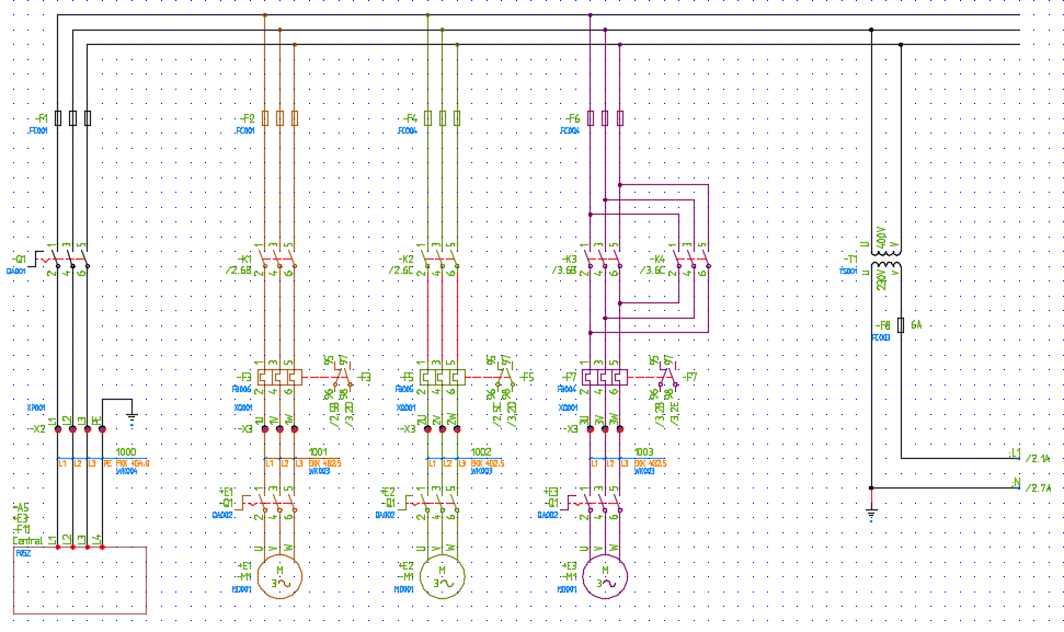
In the picture below, the two other motor circuits have also been made part of options, “Testoption 2” and “Testoption 3” respectively.
All three options are active and therefore visible.

Figure 2273: The first motor circuit belongs to ”Testoption 1” with colour 32, the second to ”Testoption 2” with colour 64 and the third to ”Testoption 3” with colour 224.
To deactivate or activate options, you use the Modify command. A detailed description is available using the link.