|
<< Click to Display Table of Contents >> Create a Hyper Dynamic Contact Mirror |
  
|
|
<< Click to Display Table of Contents >> Create a Hyper Dynamic Contact Mirror |
  
|
Start by finding out where to place the Hyper Dynamic Contact Mirror that you are going to create. Then select the Hyper Dynamic Contact Mirror macro in the c - Miscellaneous resource category in the Symbol Insert Tool, as shown in the figure below.
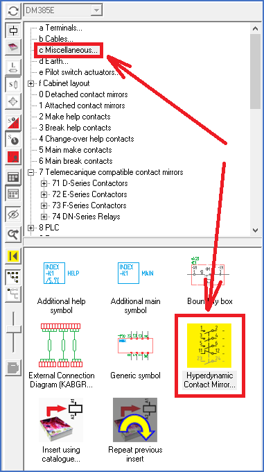
Figure 1489: You find the "Hyper Dynamic Contact Mirror..." macro under Resource Category "c - Miscellaneous".
First decide where to insert the new contact mirror, by placing the insertion point properly, normally where the horizontal and vertical lines meet, like shown in the figure below.
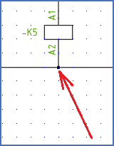
Figure 1490: A suitable place for the insertion point
The Hyper Dynamic Contact Mirror Dialogue box is then displayed, as shown in the figure below.
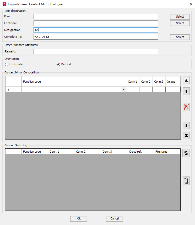
Figure 1491: The "Hyper Dynamic Contact Mirror Dialogue" box
When the dialogue box appears, you should first specify the orientation of the contact mirror in accordance with the drawing sheet you are working in. (In the sample showed in the figures here, the orientation is “vertical”).
Then specify the item designation, either by manually typing it in the Designation field, or by using the Select button for Complete Item Designation (Complete i.d.).
When you have done this, the dialogue box will appear like in the figure above.
Next step is to specify the composition of the contact mirror by selecting the function code of each contact. You do this in the Contact Mirror Composition section of the dialogue box.
Let us assume that you are going to create a contact mirror with three main contacts, one break, and two make contacts. The connection point numbers of the main contact should be 1, 2, 3, 4, 5 and 6. The connection point numbers of the break contact should be 11, 12. The connection point numbers of the make contacts should be 23, 24 and 33, 34 respectively.
Each line in the Contact Mirror Composition section refers to a contact in the contact mirror that is being created.
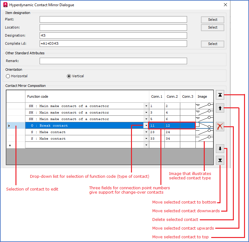
Figure 1492: The "Contact Mirror Composition" section of the "Hyper Dynamic Contact Mirror Dialogue" box
Please refer to the figure above for an overview of the Contact Mirror Composition section of the dialogue box.
Start by specifying the types of the contacts by selecting proper function codes.
The most common contact types are listed in the table below.
Function code |
Description |
|---|---|
S |
Make help contact |
O |
Break help contact |
W |
Change-over help contact |
SH |
Make main contact |
You will find a complete list of available contact types in the Technical details topic, more specifically in The contacts sub-topic.
When you select a function code for a contact, the connection point numbers will be given default values according to common practises. Please check these connection point numbers and make any necessary adjustments.
Finally click Ok to confirm your choices, and the Hyper Dynamic Contact Mirror is ready to use.
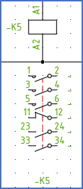
Figure 1493: Ready to use