|
<< Click to Display Table of Contents >> Connect.>> |
  
|
|
<< Click to Display Table of Contents >> Connect.>> |
  
|

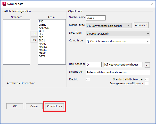
Figure 1010: The "Connect.>>" button is used to define connections points using connection point objects.
The Connection point >> button shown in the figure above, is used to add connection points to your symbol. That is done by inserting connection point objects.
The Connect.>> button is available for most symbol types, but not for mirror symbols (contact mirrors, PLC mirrors and cable mirrors), not for terminal main symbols, and not for potential reference symbols.

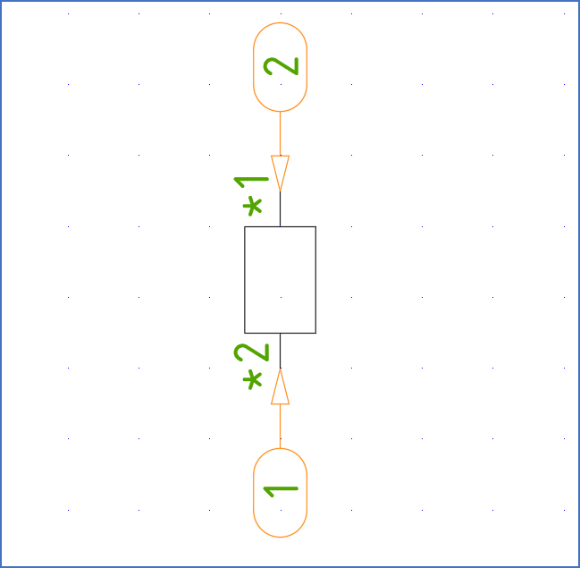
Figure 1011: Here, two connection point objects have been inserted.
The connection point object is a block with an arrow and a small balloon. Two such connection point objects are shown in the figure above.
The arrow will point at the exact place of the connection point. The direction of the arrow is identical with the direction that a line connected to the connection point in question should have. In the balloon, you will find a counting number, which is used to identify the connection point, and which is also used to define the sequence between the connections points of the symbol.
The connection point number will in most cases be stored in a visible attribute. That attribute is a part of the Connection point object, and will be editable both regarding its position and and other properties such as text height and default value.
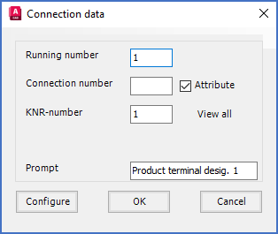
When you click the Connect.>> button, a Connection data dialogue box like shown in the figure below, will be displayed.

Figure 1012: The "Connection data" dialogue box
Please refer to the Connection data dialogue topic for a detailed description of that dialogue box.
When you click the OK button the Connection data dialogue, you will be able to insert the Connection Point Object, or in other words define where the connection point should be placed. Please refer to the topic named Specify position and direction of connection point, where all details about that are described.