|
<< Click to Display Table of Contents >> Adjust attribute definitions |
  
|
|
<< Click to Display Table of Contents >> Adjust attribute definitions |
  
|
Many times when creating new symbols or editing existing ones, you will need to adjust attribute definitions in one way or the other.
•You may need to move them.
•You may need to change text justification, for example from right adjusted to centred.
•You may need to make other changes.
In a separate sub-topic - How the attributes should be positioned - you will find general advice about how the result should be.
How you adjust attribute definitions, is described below.
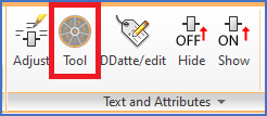
Moving and rotating attribute definitions can be done with ordinary AutoCAD commands like MOVE and ROTATE, but you can also use commands that are specially designed for attributes, like the Attribute Adjustment Tool, which is very effective in many situations.

Figure 1163: The "Attribute Adjustment Tool" is found in the "Home" tab, "Text and Attributes" panel.
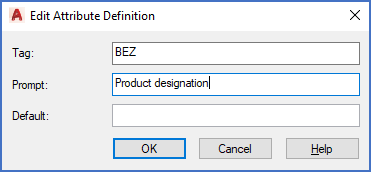
Simply double clicking an attribute definition gives access to the Edit Attribute Definition dialogue box, with which you can adjust attribute name (tag), prompt, and default.

Figure 1164: You access the "Edit Attribute Definition" dialogue box by double-clicking an attribute definition.
Other attribute properties can be adjusted with the PROPERTIES command, which however is not the best method in most cases.
You can create user defined attributes by copying existing attributes with the COPY command, and then adjust the name of the copy, for example by double-clicking it.
The table below lists suitable ways of adjusting attribute definitions in different ways. The method that in most cases is considered to be best for each operation, is marked in green.
Operation |
Standard AutoCAD command |
Adjust text and attributes |
Attribute adjustment tool |
|---|---|---|---|
Delete |
ERASE or <DELETE> button. Recommended. |
N/A |
N/A |
Move |
MOVE In most cases, you need to adjust the snap to 0.25 mm, and turn ORTHO off. Afterwards, you must set the snap back to the original 2.5 mm, and turn ORTHO on again. |
You can move several attribute definitions at once, but you need to select them one by one. |
You can move several attribute definitions at once, and you can select them all at once using a window or crossing. Recommended. |
Rotate |
ROTATE
|
You can rotate several attribute definitions at once, but you need to select them one by one. |
You can rotate several attribute definitions at once, and you can select them all at once using a window or crossing. Recommended. |
Change text justification |
PROPERTIES Not recommended. |
Multiple attribute definitions can be adjusted at once, but you must select them one by one. |
Multiple attribute definitions can be adjusted at once, and you can select them all at once using a window or crossing. Recommended. |
Change text size |
PROPERTIES Not recommended |
N/A |
Multiple attribute definitions can be adjusted at once, and you can select them all at once using a window or crossing. Recommended. |
Change layer |
Recommended method: Set the desired layer as current, and then use the Move object to current layer command. Do not forget to reset layer 0 as current afterwards. |
N/A |
N/A |
Change prompt |
Double-click. Recommended. |
N/A |
N/A |
Change default |
Double-click. Recommended. |
N/A |
N/A |
Change attribute name (tag) |
Double-click. Recommended. |
N/A |
N/A |
Copy |
COPY. Recommended. |
N/A |
N/A |
Change the invisible flag |
Do not use the "invisible" attribute property. Place the attribute in the HIDE layer instead. |
N/A |
N/A |