|
<< Click to Display Table of Contents >> Example of multiple level designations |
  
|
|
<< Click to Display Table of Contents >> Example of multiple level designations |
  
|
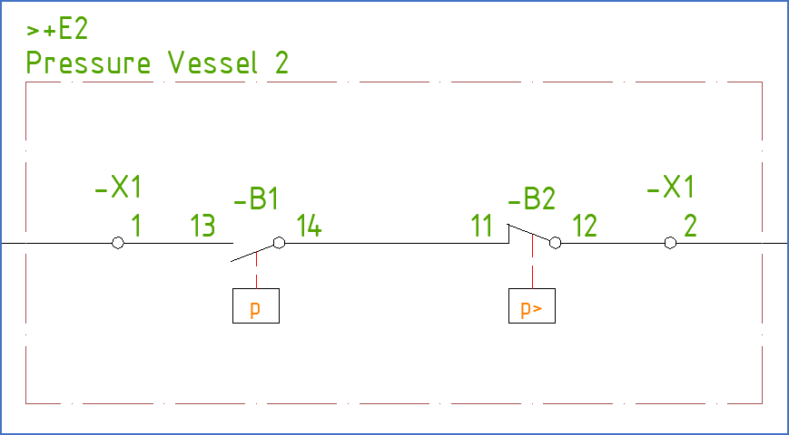
The example below comes from the description of boundary boxes in the Tutorial.
A boundary box defines a function (plant), location, and/or product (circuit) that differs from the rest of the circuit diagram, which means that it differs from what is specified in drawing frame, in most cases in the upper left corner.

Figure 373: A boundary box for location “+E2”
•In the current IEC1346 standard, the function-oriented high-level designation, which in older standards like the IEC750 was called “plant”, is now simply referred to as “function”. In the menus of cadett ELSA, “function” is referred to as “plant”.
•In IEC1346, “location” is still called “location”, in the same way as in the old standard. “Location” is also the term used in the menus.
•A third aspect – “product” – has been added in IEC1346, in parallel with function and location. “Product” is referred to as “Circuit” in the menus of cadett ELSA.
Please note that what is being said further on here about function and location is also valid for the product aspect.
A boundary box defines function (plant), location or product (circuit), for all symbols within the box. As an alternative, it is possible to enter the same information directly in the attributes of the symbols, but a boundary box is in most cases clearer, and easier for the reader of the documentation to interpret.
The whole drawing sheet may be regarded as one big boundary box. That is the reason for placing function, location, and product in the upper left corner of the drawing frame, as the IEC1082 standard stipulates, and which you can see examples of in the demonstration projects of cadett ELSA.
According to IEC1346, and in cadett ELSA, boundary boxes can be interpreted in two different ways, depending on the kind of item designations that is used. Item designations in multiple levels is one alternative, while a “flat structure” without levels is another. Which way to work is controlled by the project parameters.
•Item designations in multiple levels, is probably the most common case. Most demonstration projects that are included in the delivery of cadett ELSA are for example configured that way.
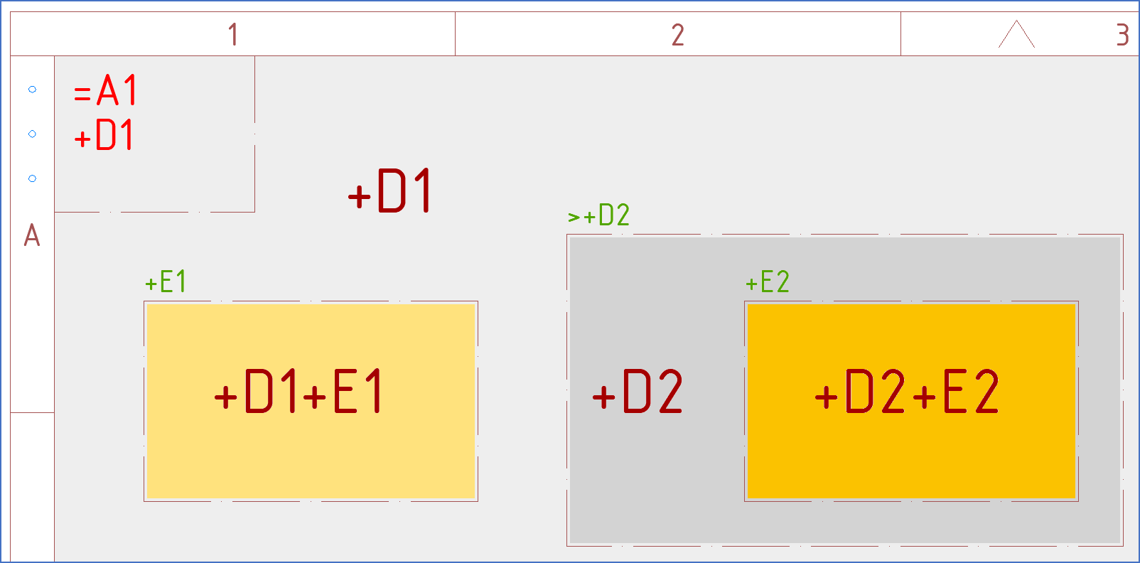
In that case, boundary boxes inside other boundary boxes symbolise sub-levels. Designations such as function (plant) and location will be added for each level from the drawing frame and inwards.
To “start from scratch”, to define a designation like location at the top level, a greater than-character (“>”) is used.
•Using item designations without levels – the “flat” variant – is common for relatively small projects with a limited number of locations or functions, like for instance the documentation of a single cabinet. To introduce multiple levels in projects of that size, would not add any benefits. An unnecessary complexity would be added though.
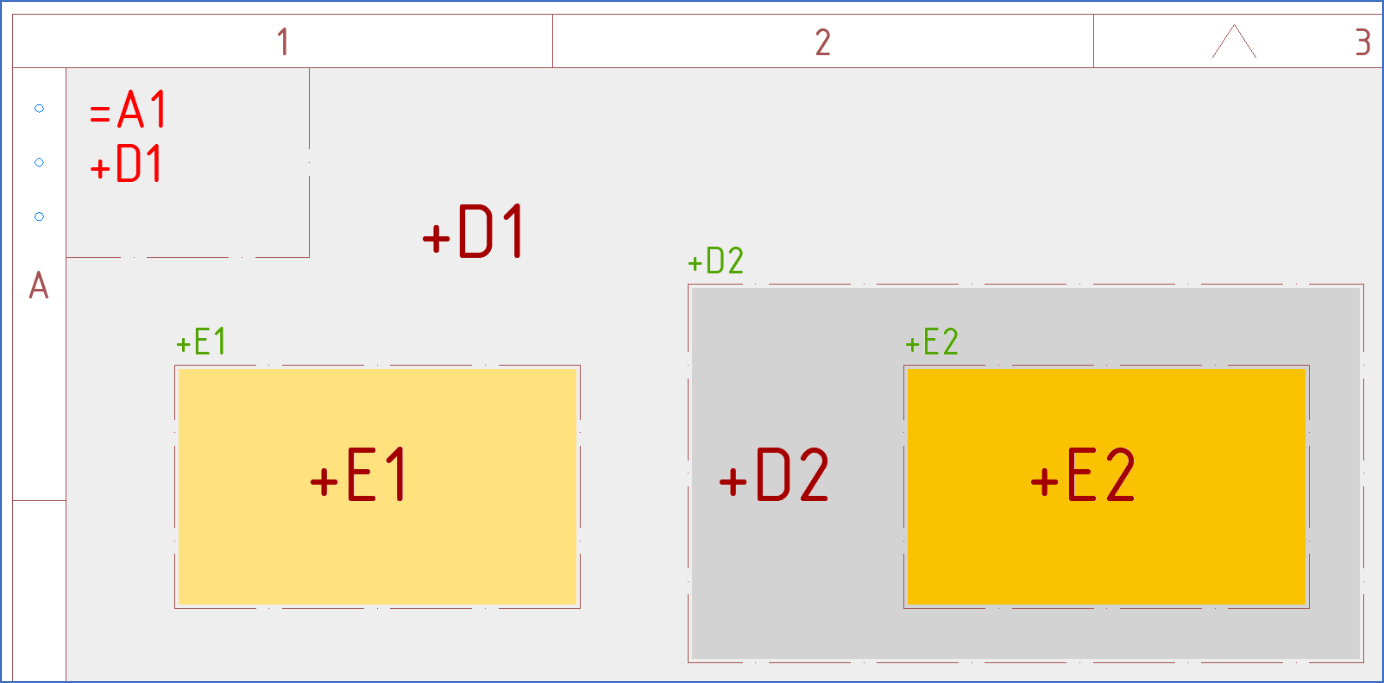
In “the flat case”, boundary boxes inside other boundary boxes simply override the designations of the surroundings, like what is defined in the drawing frame. A boundary box then defines an exception from the surrounding area in the drawing sheet.
The greater than character is not used for this kind of item designations.
Please refer to illustrations in the two figures below.

Figure 374: This figure illustrates how location is calculated for "boxes in boxes" and the use of "greater than" for multiple level item designations.

Figure 375: This figure illustrates how location is calculated for "boxes in boxes" when multiple level designations are not used.
The boundary box constitutes no device. It only adds information to symbols within the box.
The boundary box usually looks like a dashed rectangle with a designation for function (plant) or location in the upper left corner. Please refer to the first figure of this sub-topic.