|
<< Click to Display Table of Contents >> DXF forms for DIN cable and terminal plans |
  
|
|
<< Click to Display Table of Contents >> DXF forms for DIN cable and terminal plans |
  
|

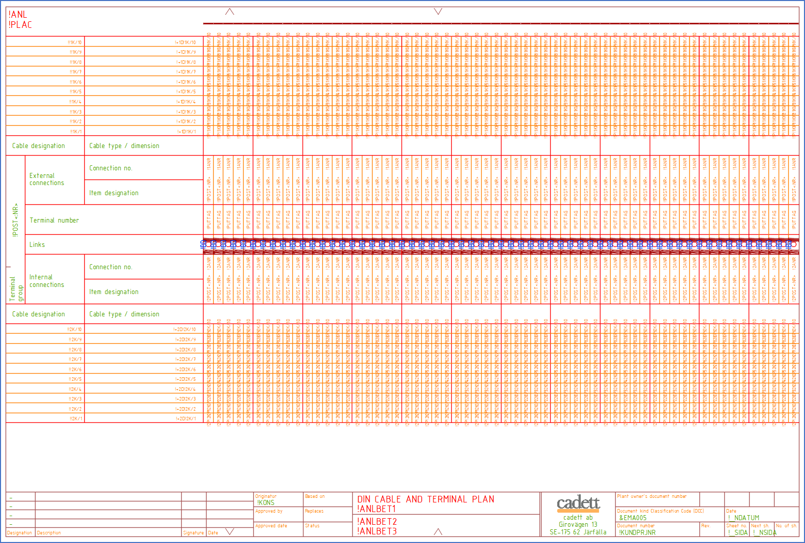
Figure 1526: A DXF form for a DIN cable and terminal plan
The example shown in the figure above clearly visualises the fact that a DXF form for a DIN cable and terminal plan is one of the most complex DXF forms in existence.
Only DXF forms are fully supported for DIN cable and terminal plans.
A form of this kind resembles an ordinary terminal list, but involves extended cable information.
The example that is included at delivery of cadett ELSA, and which is shown in the figure above, is oriented vertically. This means that it is rotated 90 degrees compared to a standard terminal list. This must be accounted for when preparing the form.
Links, both long and short, are supported in DIN cable and terminal plans. Report variables for them must be given special treatment when preparing DXF forms where they are included. Please refer to the Preparing a DXF form topic.
The central part of the form defines an ordinary terminal list, with report variables for each terminal according to the table below.
Report variable |
Description |
|---|---|
!PUTTAG |
Terminal number |
!1POST<:NR> |
Item designation for connected device on the external side. For terminals, the terminal number is excluded. |
!1ANR |
Connected connection point number on the external side. For terminals, this is the terminal number. |
!2POST<:NR> |
Item designation for connected device on the internal side. For terminals, the terminal number is excluded. |
!2ANR |
Connected connection point number on the internal side. For terminals, this is the terminal number. |
Links are defined with report variables in exactly the same way as in ordinary terminals lists, with report variables for each terminal according to the table below.
Report variable |
Description |
|---|---|
!1BY |
Long links on the external side |
!2BY |
Long links on the internal side |
!BD |
Short links in the middle |
The title field is defined in the same way as for other DXF forms. Some examples of report variables used there are listed in the table below.
Report variable |
Description |
|---|---|
!ANLBET1 |
Unit description 1 from the project parameters |
!ANLBET2 |
Unit description 2 from the project parameters |
!ANLBET3 |
Unit description 3 from the project parameters |
!KONS |
Signature 1 (originator) from the project parameters |
!KUNDPRJNR |
Document number from the project parameters |
!_NDATUM |
Date |
!_SIDA |
Sheet number |
!ANL |
Function (plant) |
!PLAC |
Location |
The "header" to the left, contains variables for terminal group name, and cables as a whole, with cable item designations, and cable electrical data. Variables for that are listed in the table below.
Report variable |
Description |
|---|---|
!POST<:NR> |
Complete terminal group name |
!!1K/1 |
Item designation for cable number 1 on external side |
!!1K/2 |
Item designation for cable number 2 on external side, and so on... |
!+1D!1K/1 |
Electrical data for cable number 1 on external side |
!+1D!1K/2 |
Electrical data for cable number 2 on external side, and so on... |
!!2K/1 |
Item designation for cable number 1 on internal side |
!!2K/2 |
Item designation for cable number 2 on internal side, and so on... |
!+2D!2K/1 |
Electrical data for cable number 1 on internal side |
!+2D!1K/2 |
Electrical data for cable number 2 on internal side, and so on... |
Additionally, cable core numbers are specified for each terminal on both sides, using variables listed in the table below.
Report variable |
Description |
|---|---|
!1P!1K/1 |
Cable core number for cable number 1 on external side |
!1P!1K/2 |
Cable core number for cable number 2 on external side, and so on... |
|
|
!2P!2K/1 |
Cable core number for cable number 1 on internal side |
!2P!2K/2 |
Cable core number for cable number 2 on internal side, and so on... |
Please note, that in order to calculate the information for a DIN cable and terminal plan, the maximum number of terminals, as well a the maximum number of cables on each terminal side, must be known. Those values are part of the report definition. Please refer to the Settings for DIN cable and terminal plans sub-topic.
Please also note, that standard report variables for cable item designations, cable electrical data, and cable core numbers, as described by the two last tables above, are included at delivery for a maximum of 20 cables on each terminal side. Would you need more than that, you can add as many additional report variables as you need. The software supports any number. The only reason for the limitation to 20, is that nobody has asked for more.