|
<< Click to Display Table of Contents >> 3. Edit |
  
|
|
<< Click to Display Table of Contents >> 3. Edit |
  
|

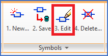
Figure 970: The "3. Edit" command
The 3. Edit command prompts you to select a symbol to edit. To be able to do that, you must of course first have inserted the symbol that you want to edit.
When you have selected a symbol that way, the symbol will be "opened for editing", which means an "extended exploding" of the symbol, or in other words that the block is exploded so that individual graphical objects, like lines and circles, become editable, the attributes will be visible and editable, and finally, Symbol Generator Objects will be inserted to graphically display more abstract data such as connection points, the insertion point, and more.
When the symbol has been "opened" this way, you can make any changes that you want, and thereafter save the result with the 2. Save command.
Moving a connection point or the insertion point is simply done by moving the corresponding Symbol Generator Object. The ordinary MOVE command works fine for that purpose.
Changing the direction of a connection point can in a corresponding way be done with the ROTATE command.
To change other properties of a connection point, like the default connection point number, is done by double-clicking the Connection Point Object, and make the desired changes in the dialogue box that is displayed.
In a corresponding way, you can change information belonging to the symbol itself, like the name of the symbol, and the Resource Category, by double clicking the Symbol Object, and make the desired changes in the Symbol data dialogue that is then displayed.