|
<< Click to Display Table of Contents >> Editor for document codes |
  
|
|
<< Click to Display Table of Contents >> Editor for document codes |
  
|
Two separate sets of document code definitions are available in cadett ELSA:
•One central set of definitions
•One set of definitions for each project
Both definition sets are edited directly from the Drawing Manager.
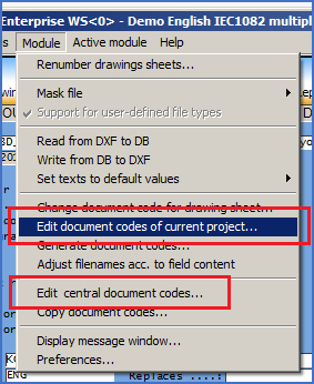
In the Module pull-down menu in the Drawing Manager you will find two commands that are used for that:
•Edit document codes of current project...
•Edit central document codes …
The same editor is used for both purposes, but it is working towards two separate databases.

Figure 612: Commands to edit document codes.
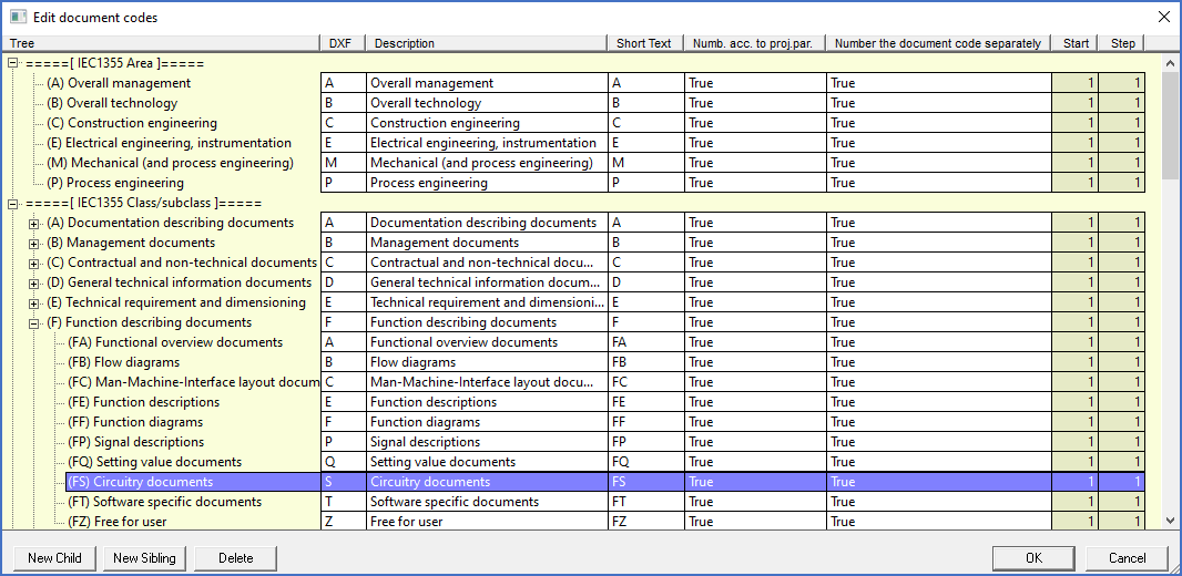
The dialogue box that is displayed when you select one of these commands looks like the picture below shows.

Figure 613: This figure shows the dialogue that is used to edit document codes. Please note that multiple structures in parallel are handled.
Using the buttons named New child, New sibling and Delete, you can easily add new document codes or remove old ones. You modify existing document codes by simply selecting the one to change and then modifying it directly in the dialogue.
•New child means creating a new document code in the level below the selected one.
•New sibling means creating a new document code in the same level as the selected one.
•Delete means deleting an incorrect or otherwise unwanted document code.
To create an entirely new tree, you select the top level of an existing tree and click New sibling.
As shown in the dialogue box, there are several settings for each document code. Which they are and what significance they have are described in the following.
In general, however, settings that control sheet numbering and similar are taken from the last document level. Settings in higher levels are therefore irrelevant.
Example (from the full IEC1355 implementation):
Drawing sheet: EFS______001
In this case, the area is defined as "E" is for "Electrical drawing", the class is defined as "F" for "Function" and the subclass is defined as "S" for "Circuitry". Sheet numbering and more are then controlled by the subclass "S" since it comes last, next to the sheet number. The settings that apply to the area and to the class have no significance at all.
The meaning of the different settings is as follows:
Setting |
Explanation |
|---|---|
DXF |
This setting contains the file name characters that are associated with the document code in question and which are used to specify the document code in the file name.
The DXF setting may consist of one or multiple characters. The maximum number of characters that are currently supported is 10.
|
Description |
The Description is used to explain the use of the document code in question in plain language, like "Circuit diagram".
|
Short text |
The Short text is - no surprise - a shorter description than the description. It text can be used for a link to the drawing manager, for example as the default value for one of the attributes in the title field.
One example of the latter would be a document code associated with a location, where the Description could describe the location in question, for example "Control cabinet 1", while the Short text could be "+S1". The Short text could then be used as default for the location in the upper left corner of the drawing frame.
|
Number according to project parameters |
This settings can either be True or False.
True means that the drawing sheets that belong to this document code are numbered according to the settings for start and step values specified by the project parameters of the current project. False, on the other hand, means that the start and step values specified for the particular document is used. Those settings are found in the columns to the right.
|
Number the document code separately |
This setting can also be either True or False.
True means that drawing sheets that belong to this document code are numbered in a separate individual numbering series. If for example circuit diagrams and cabinet layouts both have this setting set to True, and use the same start and step values, like 1 and 1, you would have the circuit diagram sheets numbered from 1 and upwards, and that the cabinet layouts also numbered from 1 and upwards. In other words, you will have two sheets with the same sheet number (one circuit diagram and one cabinet layout).
Another possibility is to use separate Start values for the sheet numbering. The circuit diagrams may for example have a start value of 100, while the cabinet layouts have a start value of 200. That will effectively avoid the problem of multiple sheets with the same sheet number, as long as you have a maximum of 100 circuit diagrams.
False, on the other hand, means that the document code does not have an individual numbering series, but that it is numbered in a numbering series common with all other document codes that also have this setting set to False. In other words, you can have the start values for both circuit diagrams and cabinet layouts set to 1. Still, you will never get two sheets with the same Sheet number, since the circuit diagrams will end up first and the cabinet layouts thereafter. (This assumes that EFS and ETL are used, where EFS comes first alphabetically. By selecting different document codes, you could make cabinet layouts come first if you prefer that). Using settings like that, all drawing sheets will end up in one single common sequence.
|
Start |
Start is the initial value for sheet numbering of the drawing sheets that belong to the document code in question. This value is used only if Number according to project parameters is set to False.
|
Step |
Step is the step value for sheet numbering of the drawing sheets that belong to the document code in question. This value is used only if Number according to project parameters is set to False.
|