|
<< Click to Display Table of Contents >> PLC help symbol |
  
|
|
<< Click to Display Table of Contents >> PLC help symbol |
  
|
A PLC help symbol is in most cases the same thing as an I/O symbol, meaning a symbol that represents one particular in- or output of a certain kind.
The kind of I/O that a PLC help symbol represents is defined by the function code of the symbol. The function code defines a combination of three separate properties:
•Input or output
•Digital or analogue
•Number of connection points
Please refer to a separate topic name Function codes for PLC in- and outputs for a detailed list of available function codes.
The appearance of an I/O symbol can vary a lot. The IEC standard however gives some guidance. The I/O symbols of the standard IEC1082 symbol library follow the guidelines in the standard quite well.

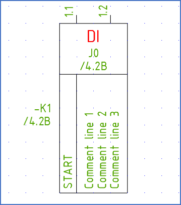
Figure 893: This is a typical I/O symbol, a vertical digital input with two connection points directed upwards. This symbol is named "SPDJ2U", and you can find it under resource category "85" in the standard IEC1082 symbol library.
An I/O symbol as described above can be booked on a PLC mirror, which symbolises a set of in- and outputs, typically an entire I/O card.
Distinguishing properties of an I/O symbol include the following:
•It connects to PLC main symbols.
•It can be mirrored by a PLC mirror.
•Typically, it does not have an index, but it can have one.
•It typically have connection points, typically 1 - 4 for digital I/O's, and 1 - 12 for analogue I/O's.
•It does not have a component type letter code.
•It must have a function code, which is used for mirror booking or to prevent mirror booking.
•The function code defines if it is a digital or analogue I/O.
•The function code also defines if the I/O is an input or output.
•Finally, the function code defines the number of connection points of the I/O.
•It can have two cross-reference attributes, one to the main symbol, and one to the PLC mirror.
•Besides from the attributes that are typical for a conventional help symbol, like item designation, remark and more, a PLC help symbol typically have the following additional attributes, specially dedicated for PLC functionality:
oI/O number (ADRESSE)
oSymbolic address (SYMBOL)
oUp to seven comments (TEXT1 - TEXT7)
•The Resource Category is typically given by the table below.
Standard resource categories for PLC help symbols (I/O symbols) |
||
|---|---|---|
Resource category |
Description |
Function codes |
85 |
Digital inputs |
#DI* |
86 |
Digital outputs |
#DO* |
87 |
Analogue inputs |
#AI* |
88 |
Analogue outputs |
#AO* |
The standard I/O symbols that are provided in the IEC1082 symbol library covers almost all practical needs. There are therefore hardly any need to create I/O symbols similar to the standard ones. The only reason for creating user defined I/O symbols is therefore if you would like them to be different from the standard symbols in one way or the other.
Possible such needs include the following:
•Smaller symbols
•A different look
•Additional user defined attributes
•Different arrangement of the attributes
•Different text sizes
The quickest and easiest way to create your own variants, is in most cases to start with a standard symbol, make the desired changes to that, and save it is a user defined symbol with a new name. To make the process as easy as possible, you should start with a symbol with the same function code as the symbol you want to create.
•Digital/analogue should match
•Input/output should match
•Number of connection points should match