|
<< Click to Display Table of Contents >> KNR1 - KNR12 |
  
|
|
<< Click to Display Table of Contents >> KNR1 - KNR12 |
  
|
The KNR fields are used for connection point numbers. The number of connection points is determined by the selected function code, and can be any number between 1 and 12.
Please note that cadett ELSA supports an unlimited number of connection points per I/O, but the lack on the market of PLC's with more than 11 connection points per I/O, makes higher numbers less useful.
The sequence of the connection point numbers for each I/O is significant for mirror booking. Therefore, please make sure to define them in a consistent manner.
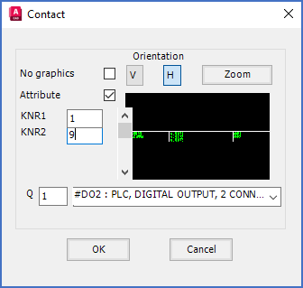
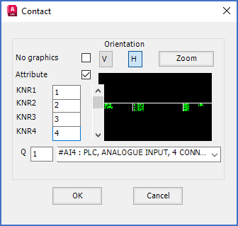
The two figures below shows how connection point numbers for a typical digital output, and a typical analogue input, can be defined.

Figure 846: The selected function code is #DO2. Therefore, the number of connection points is 2.

Figure 846: The selected function code is #AI4. Therefore, the number of connection points is 4.
Technical detail
KNR1, KNR2, KNR3, and so on, are the attribute names used in I/O symbols for connection point numbers. KNR is in fact an abbreviation for the German word "Kontaktnummer", which means "Contact number".