|
<< Click to Display Table of Contents >> KNR1 - KNR3 |
  
|
|
<< Click to Display Table of Contents >> KNR1 - KNR3 |
  
|
The KNR fields are used for connection point numbers. Make and break contacts of course only utilises the two first, while a change-over contact utilises all three.
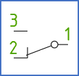
For change-over contacts, the sequence of the connection point numbers is significant, while it does not affect a make or break contact. The figure and the table below describes how the three fields are used for change-over contacts.

Figure 1133: The sequence for connection point numbers in a change-over contact
Sequence number |
Connection point |
|---|---|
1 |
The hinge |
2 |
The rest position |
3 |
The active position (make) |
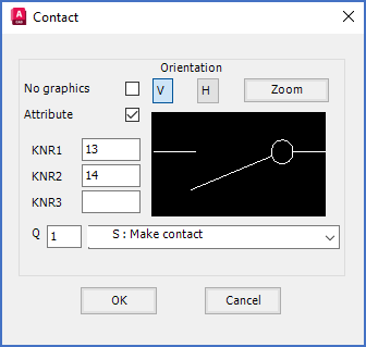
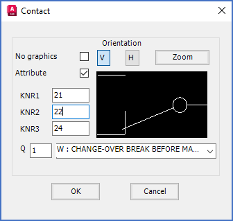
The two figures below, shows how connection point numbers for a typical make contact, and a typical change-over contact, can be defined.

Figure 1134: Only two connection point numbers are defined for a make contact.

Figure 1135: All three available connection point numbers are defined for a change-over contact.
Technical detail
KNR1, KNR2, and KNR3 are the attribute names used in contact help symbols for connection point numbers. KNR is in fact an abbreviation for the German word "Kontaktnummer", which means "Contact number".