|
<< Click to Display Table of Contents >> Electrical layers |
  
|
|
<< Click to Display Table of Contents >> Electrical layers |
  
|
These settings decide which layers that are suppose to be ”electrical”. An electrical layer is ”active” from the perspective of the OnLine Engine, while a layer that is non-electrical, is disregarded entirely.

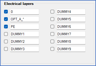
Figure 314: The figure shows the "Electrical layers" section of the "Drawing manager 1" tab in a project that uses the IEC1082 symbol library.
All objects that are located in electrical layers will be processed by the OnLine Engine of cadett ELSA, which will try to identify symbols and lines, in the best way it possibly can. All objects that are not located in electrical layers will however be ignored by the OnLine Engine.
You have the opportunity to define no less then twelve layer names which can be set as electrical. Each one of these twelve layers, can be set as electrical or not using a check-box. Defining a layer as non-electrical that way, gives exactly the same result as not defining that layer at all. A layer that should sometimes be electrical and sometimes not, is an example when it can be meaningful to define a layer here, that is not electrical.
Layer names can be specific or general using a wild-card, namely the asterisk character ("*").
PE, for example, refers to the layer that is named "PE", and nothing else.
CONT*, on the other hand, refers to all layers which have names beginning with “CONT”.
Typical electrical layers in projects using the IEC1082 symbol library are 0, PE, and OPT_A_*. 0 is there used for circuit diagrams in general. PE is sometimes used for protective earth specifically when a dashed line is desired. OPT_A_* is used for Option Handling, which is described in a topic of its own.

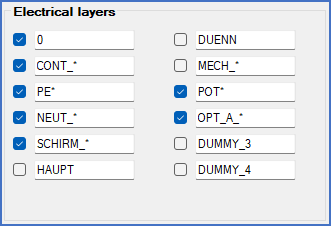
Figure 314: This example comes from a project that uses the DIN5 symbol library, which is based on a layer set that is partly different from the IEC1082.