|
<< Click to Display Table of Contents >> Editing terminals |
  
|
|
<< Click to Display Table of Contents >> Editing terminals |
  
|
You can modify a terminal that is already inserted in the circuit diagram, by simply double-clicking it.
If you instead use the ordinary Ddatte/Edit command, you can select multiple terminals at once, for instance with a “window”. Another way of editing multiple terminals at once, is to select all the terminals before you double-click.

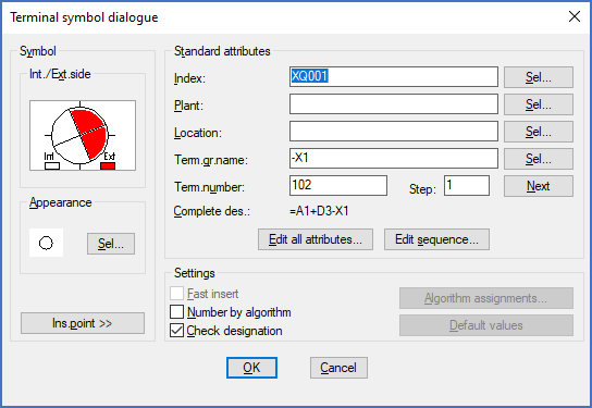
Figure 1632: When modifying existing terminals, some fields in the “Terminal symbol dialogue” are greyed out.
Regardless, you will get one dialogue box for each terminal, in the same order as you have selected the terminals. The dialogue box is the same as when you insert terminals. Some alternatives are however greyed out in this situation since you only work with one terminal at a time.
You may change attributes, like terminal number and index, and even the orientation of internal and external side, and do some modifications in the appearance of the terminal.
This method is however inconvenient for renumbering multiple terminals, since you must change each terminal number separately.
There are at least two better ways of doing that:
1.You can make an automatic renumbering of selected terminals from the Terminal list in Dynamic Online I.
2.You may use the Numbering of text and attributes feature to make a manual renumbering of selected terminals. This is described in a separate topic.
If you want to change the internal and external sides of multiple terminals at once, there is a convenient method of doing that available as well. Please refer to a separate feature named the Terminal Direction Editor.